Daniel 3812 Liquid Ultrasonic Flow Meter Installation Manual Section 4: Configuration
3-9000-765 Rev H May 2015
Using a Field Communicator to configure the meter 95
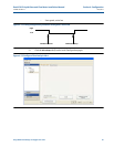
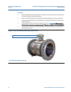
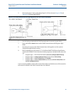
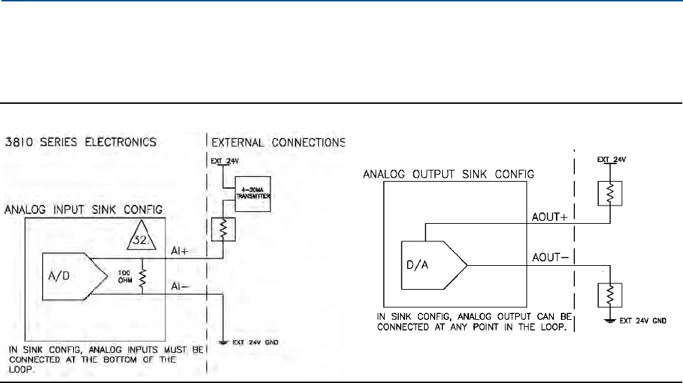
5. Wire Analog Input 1 (AI1) and Analog Output 1 (AO1) as shown in Figure 4-20 and
Appendix A, drawing DMC-004936.
Figure 4-20 Field Communicator wiring diagram for the 3810 Series electronics
6. Use the leads provided with the Field Communicator to connect to your device.
7. Press and hold the
Power button on the Field Communicator until the green light
blinks.
8. Use the touch screen on the Field Communicator, the keypad or use the stylus to
na
vigate through the device menus.
9. Refer to the Menu tree in Section D.1.1 of the Daniel HART Field Device Specification
ma
nual (P/N 3-9000-761) for the device fast key sequences. Included in the menu tree
are:
• Di
agram Page 1 - 3810 Series Root Menu;
Overview, Configure|Manual Setup
• Diagram Page 2 -
Configure|Manual Setup (continued) and Alerts Setup
• Diagram Page 3 - Service Tools|Alerts and Variables
• Diagram Page 4 -
Service Tools|Variables (continued), Service Tools|Trends, and
Service Tools|Maintenance
If you encounter problems, refer to the contact information on the back cover of this manual or
the contacts included in the Field Communicator Users Manual.


