


NurseCall Relay Unit Description | en 9
Bosch Security Systems User Manual F.01U.252.722 | V1 | 2011.12
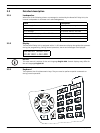
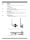
2.1.3 Front view
1. LED Indicator
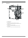
2.1.4 Relay Unit rear view
1. RS-485 connector.
See Section A.5.4 RS-485 socket (unit rear), page 34 for wiring.
2. Antenna connector
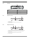
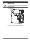
2.1.5 Relay Plus Unit rear view
1. RS-232 connector, used for the printer/display interface of the Relay Plus Unit.
See Section A.5.3 RS-232 socket (Relay Plus Unit rear), page 34 for wiring.
2. RS-485 connector.
See Section A.5.4 RS-485 socket (unit rear), page 34 for wiring.
3. Antenna connector
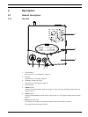
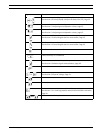
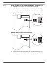
Status LED
Standby mode (normal operation) Green (permanent)
Backup battery low Green (blinking)
Power supply disconnected Green (flashing)
Help, assistance or fire Red (blinking)
1
1 2
12 3