


18 en | Installation NurseCall Relay Unit
F.01U.252.722 | V1 | 2011.12 User Manual Bosch Security Systems
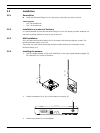
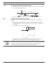
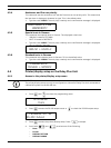
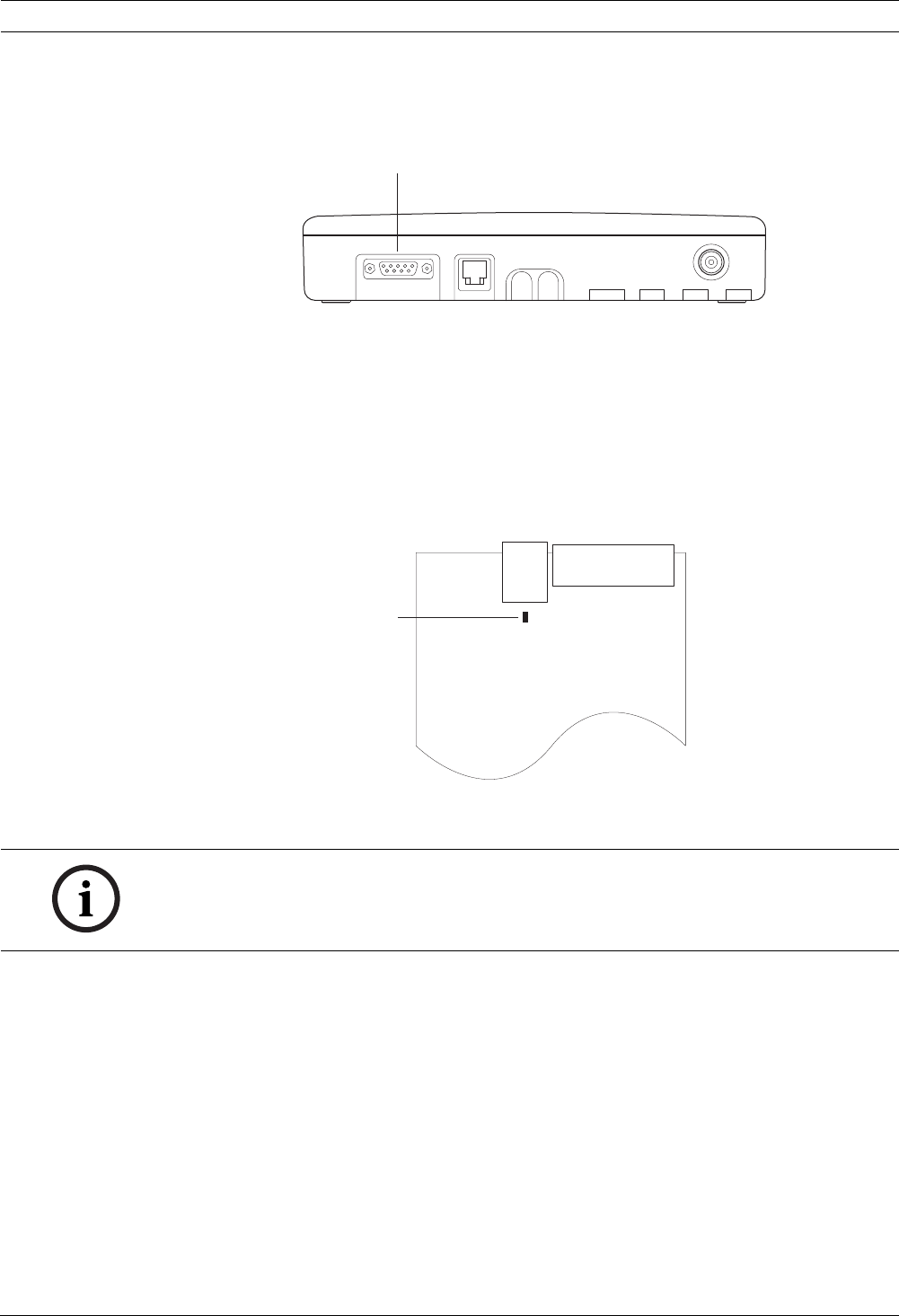
3.2.8 Connecting the RS-232 to the Relay Plus Unit
Connect the printer or display device to the 9-pole SUB-D connector (1) at the rear part
of the housing of the Relay Plus Unit.
For connector wiring, see Section A.5.3 RS-232 socket (Relay Plus Unit rear), page 34.
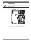
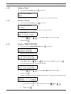
3.2.9 Setting the 100 Ohm termination jumper
Within the NurseCall Main or Relay Units, the RS-485 interface can be configured with a
jumper.
1. Disassemble the unit as described in Section 6.5.1 Disassembling the unit, page 29.
2. Remove the communication board as described in Section Removing the communication
board, page 29.
3. Put the 100 Ohm termination jumper J112 (1).
4. Assemble the communication board and the unit. This is basically the reverse of the
disassembling procedure, see Section 6.5.1 Disassembling the unit, page 29.
1
1
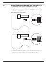
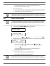
NOTICE!
If you do not want to disassemble the NurseCall Relay Unit, you also can short-out pins 3 and
4 of the connector. This has the same effect as the jumper setting described above.
See Section A.5.4 RS-485 socket (unit rear), page 34 for connector wiring.