


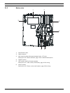

12 en | Description NurseCall Relay Unit
F.01U.252.722 | V1 | 2011.12 User Manual Bosch Security Systems
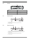
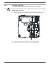
2.2.4 RS-485 interface
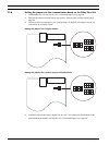
One NurseCall Main Unit and up to 32 NurseCall Relay Units can be connected by a RS-485
bus. The bus must be connected to pins 2 and 5 of the RS-485 socket.
For connector wiring, see Section A.5.4 RS-485 socket (unit rear), page 34.
In this configuration, you always should connect the NurseCall Main Unit first. The NurseCall
Relay Units must then be connected to the RS485-bus one by one, not at the same time.
Relay output
In the same connector, a potential free contact is available. It is a low current switching
contact. The relay (potential free, switching power max. 48 V / 0.5 A) is activated at a call for
help, call for assistance or fire alarm. This relay can be set as closing or switching contact
(cycle of 10 seconds on / 10 seconds off). This feature can be used to drive a signal lamp for
example.
For connector wiring, see Section A.5.4 RS-485 socket (unit rear), page 34.
For relay setting, see the user manual of the NurseCall Main Unit.
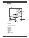
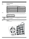
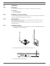
2.2.5 Antenna
The antenna is connected to the NurseCall Relay Unit using the adapter supplied with the
unit.
See Section 3.2.4 Installing the antenna, page 14.
NOTICE!
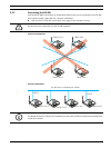
Keep polarity equal when connecting further units to the RS485 bus!
NOTICE!
Maximum RS485-bus length: 1200 m.
Use only one twisted pair cable for the interconnection.
NOTICE!
The receiver units located at the two ends of the bus must be terminated with a 100 Ohm
resistor. See Section 3.2.7 Connecting the RS-485, page 17 for more information about the
jumper setting.