


5
The trolley width shall be adjusted by
loosening the jam nuts on the traverse drive
side of the threaded rods at each end of the
hoist. If necessary, lubricate the frame
alignment bars with penetrating oil before
attempting to adjust trolley width. The trolley
side may then be pushed or driven into
position by turning the adjusting nuts on the
treaded rods. Adjust nuts on each side of
the hoist simultaneously to avoid binding.
After adjusting the trolley to the proper
width, tighten all adjusting nuts and the
clamp collar, and re-secure the electrical
conduit/cable. Verify that the geared wheels
mesh properly with the traverse drive
pinions. Using proper equipment, carefully
lift the trolley and hoist and install on the end
of the beam. Lubricate the wheel gear and
pinion (WG, Section IV, Paragraph 4-3).
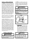
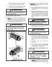
b) CLOSED-END BEAM
: For trolleys which
are to be mounted along the span of a beam
not having open ends, the trolley must be
adjusted in the same manner as described
above to a width that allows clearance
between the axles and the beam flange.
Using proper lifting equipment, the trolley
and hoist must then be lifted to the beam
where it is to be installed. Once in position,
adjust the spacing between the trolley wheel
flanges to be 3/16”-1/4”” greater than the
exact width of the beam flange (See Figure
2-1). After tightening all adjusting bolts, the
clamp collar, and all electrical conduit/cable
clamps, carefully set the trolley on the beam.
Lubricate the wheel gear and pinion (WG,
Section IV, Paragraph 4-3).
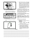
2-3. CONNECTING HOIST TO ELECTRICAL
SERVICE. Electrical service to the hoist may be
power cable or a guarded system having sliding
shoe or wheel type collectors.
WARNING
Be certain that electrical power supply is
OFF and locked in the open position
before attempting any electrical
connections to the hoist. This equipment
must be effectively grounded according
to the National Electric Code ANSI/NFPA
70, or other applicable codes. If the
grounding method used is through the
trolley wheels, then each section of track
must be grounded by metal-to-metal
connection to the building ground.
Certain environments may prevent
proper grounding by this means. In this
case a separate grounding conductor
should be provided.
a) Follow ANSI/NFPA 70, state, and local
electrical codes including the grounding
provisions thereof when providing electrical
service to the hoist.
b) Make electrical connections using the
appropriate wiring diagrams furnished with
the hoist. All electrical connections
, including
connections to collectors or power cord shall
be made only by qualified journeyman
electricians.
CAUTION
Power supply to hoist and trolley must
be the same voltage, frequency, and
phase that are specified on the hoist and
trolley nameplate.
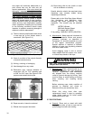
2-4. PRE-OPERATION CHECKS.
a) Check Oil Level.
(Figure 2-1) The gearcase
has been filled with oil to the proper level.
However this should be re-checked before
operating the hoist.
Check oil level by removing the plug
indicated in Figure 2-1. When properly filled,
oil should be level with the bottom of the
tapped hole. Fill to this level with oil as
specified in Paragraph 4-2.e.
b) Check Push Button Operation and Phasing.
To properly check the phase of the hoist,
follow these steps:
(1) With “POWER OFF” operate all the push
buttons and determine that they do not
bind or stick in any position.
WARNING
If any push button binds or sticks in any
position – DO NOT TURN POWER ON –
determine the cause and correct the
malfunction before operating.
(2) Connect hoist to power source.
WARNING
On three phase hoists it is possible to
have “Reverse Phasing” causing the
block to lower when the “UP” button is
depressed. When this condition exists
the automatic limit switch is inoperative
and hoist operation will be dangerous.