


22
(3) Connect the brake leads to the terminal
block on the brake body.
(4) Install the forward fan mounting retaining
ring and install the fan. Install the rear
retaining ring. Install the fan shroud and
bolts.
(5) Test hoist per Section V, Paragraph 5-13.
5-11. INSPECTION OF HOIST TRAVERSE
DRIVE.
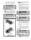
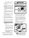
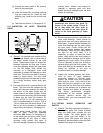
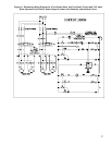
Figure 5-10. Traverse Drive Arrangement.
a) General.
The traverse drive consists of four
single flange wheels, two on each side of
the beam, carried directly by the hoist
frame. These wheels rotate on sealed ball
bearings supported by fixed pins. Pinions
drive two opposing wheels with gear teeth
cut into the flange. Both pinions are
mounted on a hexagonal drive shaft
supported by sealed ball bearings at each
hoist side. The pinions are held in place by
means of clamp collars. The drive shaft
passes through one hoist side and is driven
by a single reduction hollow shaft gear
reducer.
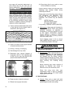
b) Ensure that the hoist is properly fitted to the
beam. The hoist must be centered on the
beam with clearance between the sides of
the bottom of the beam flange and the
inside faces of the wheel flanges. Proper
clearance must exist along the entire length
of beam that the hoist can traverse. An
amount of 3/32 to 1/8 inch clearance per
side is recommended for a total of 3/16 to
1/4 inch wider than the beam flange. If too
little or too much clearance is determined,
adjust trolley per Section II, Paragraph 2-2.
c) Inspect wheel treads, flanges, and gear
teeth for wear. Check for adequate
lubrication (WG, Section IV, Paragraph 4-7)
on the wheel gear and pinion mesh. Check
wheel bearings for any signs of wear,
including rough rotation and signs of
lubricant leakage. Replace all damaged or
missing items. Wheels must always be
changed in opposing pairs and drive
wheels should be changed when the drive
pinions are replaced.
CAUTION
Ensure that the cross shaft is properly
positioned and locked into place by
means of the clamp collars. Failure to
do so may allow the drive shaft to
contact the rope on the rope drum (B
frame) or the hoist gearcase (C frame
hoist).
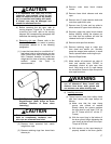
d) Examine the drive pinions, cross shaft, and
cross shaft bearings. Check pinions for
gear tooth wear and proper alignment with
wheel gear. A spacer washer between the
cross shaft bearings and the pinion aligns
the gear mesh. Clamp collars hold the
pinions and spacer washers tight against
the bearings. Verify that the clamp collars
are tight on the cross shaft. If it is
necessary to adjust or reset the clamp
collars, verify that the hex shaft surface is
free of mechanical damage and oil before
tightening the clamp collars. Drive pinions
must be replaced as sets and should be
replaced along with the drive wheels. The
cross shaft bearings are sealed for life and
should be replaced at any sign of
mechanical wear or lubricant leakage.
e) Inspect the traverse gearbox and motor.
Look for signs of rough operation,
mechanical damage or lubricant leaks.
Inspect the hollow bore and hexagonal
drive shaft for wear. Verify that the four
bolts that hold the gearbox to the trolley
frame and the four bolts that hold traverse
motor to the gearbox are all present and
tight. Replace and tighten as necessary.
The factory recommends complete
replacement of the traverse gearbox.
However, gearbox service may be
available from you local authorized Yale
repair center.
5-12. TESTING BLOCK OPERATED LIMIT
SWITCH.
a) General.
The block operated limit switch is
a secondary upper limit switch actuated
when the lower block contacts the limit
switch weight. The rotary geared limit
switch (screw type limit switch) is the
primary upper limit switch and must be
temporarily disconnected to allow the block
operated limit switch to be tested.