


19
spur. The gear shafts are supported with
ball bearings housed in the back of the
case and in the cover. The input helical
pinion is cut directly into the motor shaft. An
oil seal housed in the gear case at the
motor input seals the motor shaft as it
passes into the gear case. Since the entire
motor shaft is submerged in oil, anytime the
motor is removed, the oil must be drained
from the gear case. All pinions are integral
with their shafts while the gears are keyed
and pressed onto their shafts. The output
shaft passes through an oil seal in the back
of the gear case and drives the drum by
means of a crowned spline. One end of the
rope drum is supported on this output shaft.
b) Inspection and Disassembly
.
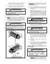
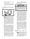
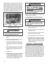
Gearcase. (See Figure 5-8.)
(1) Lower hook block to the floor and relieve all
load from ropes.
(2) Make sure power to hoist is off and locked
out.
WARNING
Before disassembly, prevent rope drum
from free spinning by wedging drum in
place with a block of wood, and resting
lower block on work surface so all
weight is off rope drum. Rope may also
be removed from hoist drum.
(3) Drain the oil from the gear case per
Section IV, Paragraph 4-2.
(4) Provide adequate means to support the
gear case cover. Once the cover is
supported, remove the two (2) shoulder
bolts, seven (7) socket head cap screws,
and nine (9) lock washers holding the
cover to the gear case. Carefully draw
the cover directly away from the gear
case, as damage to this surface will
prevent the gasket from sealing properly.
As the cover is removed, ensure that all
gear and shaft assemblies remain in the
case.
WARNING
If output shaft assembly is pulled out of
the gear case with the cover, it will
disengage from the drum allowing the
drum to drop. Be certain all shaft
assemblies stay in the case.
(5) If it is necessary to remove the output
shaft assembly from the gear case, the
rope drum must first be removed from the
hoist. See Section V, Paragraph 5-7.
WARNING
The hoist must be removed from service
and repaired on the ground for any
maintenance that requires removal of
the output shaft assembly or drum.
Only once the output shaft is free of the
rope drum, can the output shaft assembly
be safely removed from the gear case.
Provide an adequate means to support
this shaft and gear assembly before
removing, as it weighs approximately 80
lbs. (“C” Frame Hoist).
(6) The pinion shaft and gear assemblies
may be removed as necessary.
(7) Inspect all gears, pinions, bearings, and
the output shaft spline for wear, pitting, or
mechanical damage. Replace as
necessary. See Section IX, Figure 9-2 for
replacement parts. It is recommended
that gears and pinions only be replaced
as sets. Thoroughly clean the output
shaft external spline teeth before
reassembly.
(8) Assembly is opposite of removal. Use a
new gasket. Do not attempt to assemble
the cover to the gear case without a
gasket, as the spacing between bearings
will be reduced. Severe damage to the
hoist will occur if no gasket or the wrong
gasket is used. Refill gear case with new
lubricant per Section IV, Paragraph 4-2
before use. Using SG (Paragraph 4-7),
grease the spline teeth on the output
shaft before reinstalling rope drum.
(9) Test hoist per Section V, Paragraph 5-13
to ensure proper lubrication.
Hoist Motor.
(1) Lower hook block to the floor and relieve all
load from ropes.
(2) Make sure power to hoist is off and locked
out.
(3) Drain the oil from the gear case per
Section IV, Paragraph 4-2.