


29
SECTION IX – PARTS LIST
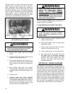
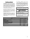
9-1. GENERAL. The parts lists and illustrations in
this section of the manual cover parts for models of
Yale “Global King” Electric hoists. A typical hoist is
shown as the basis for the exploded parts
illustrations; therefore, certain variations may occur
from the information given. For this reason, always
give the Hoist Serial Number, Catalog Number,
Motor Horsepower, Voltage, Phase, Frequency and
Capacity of Hoist when ordering parts.
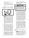
Yale “Global King” Hoists are built in two basic
frame sizes, “B” Frame and “C” Frame. To
determine the size of your hoist, measure the width
of the gearcase (see Figure 4-2.) The “B” Frame’s
gearcase has a width of 11 3/4” and the “C” Frame
has a gearcase width of 14 1/2”.
Certain parts of your hoist will, in time, require
replacement under normal wear conditions. It is
suggested that these parts be purchased for your
hoist as spares for future use. These parts are
indicated by a (†) symbol at the side of the parts
reference numbers.
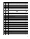
The numbers assigned to parts of our
various assemblies in our parts list are not
the part numbers used in manufacturing the
part. They are identification numbers, that
when given with the model number, permit
us to identify, select or manufacture, and
ship the correct part needed.
WHEN ORDERING PARTS OR INFORMATION
ON THIS EQUIPMENT, ALWAYS INCLUDE
MODEL AND SERIAL NUMBER ON ORDER.
WARNING
Using “Commercial” or other manu-
facturer’s parts to repair Global King
Hoists may cause load loss.
TO AVOID INJURY:
Use only Yale Hoist supplied parts. Parts
may look alike but Yale Hoist parts are
made of specific materials or processed to
achieve specific properties
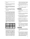
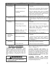
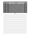
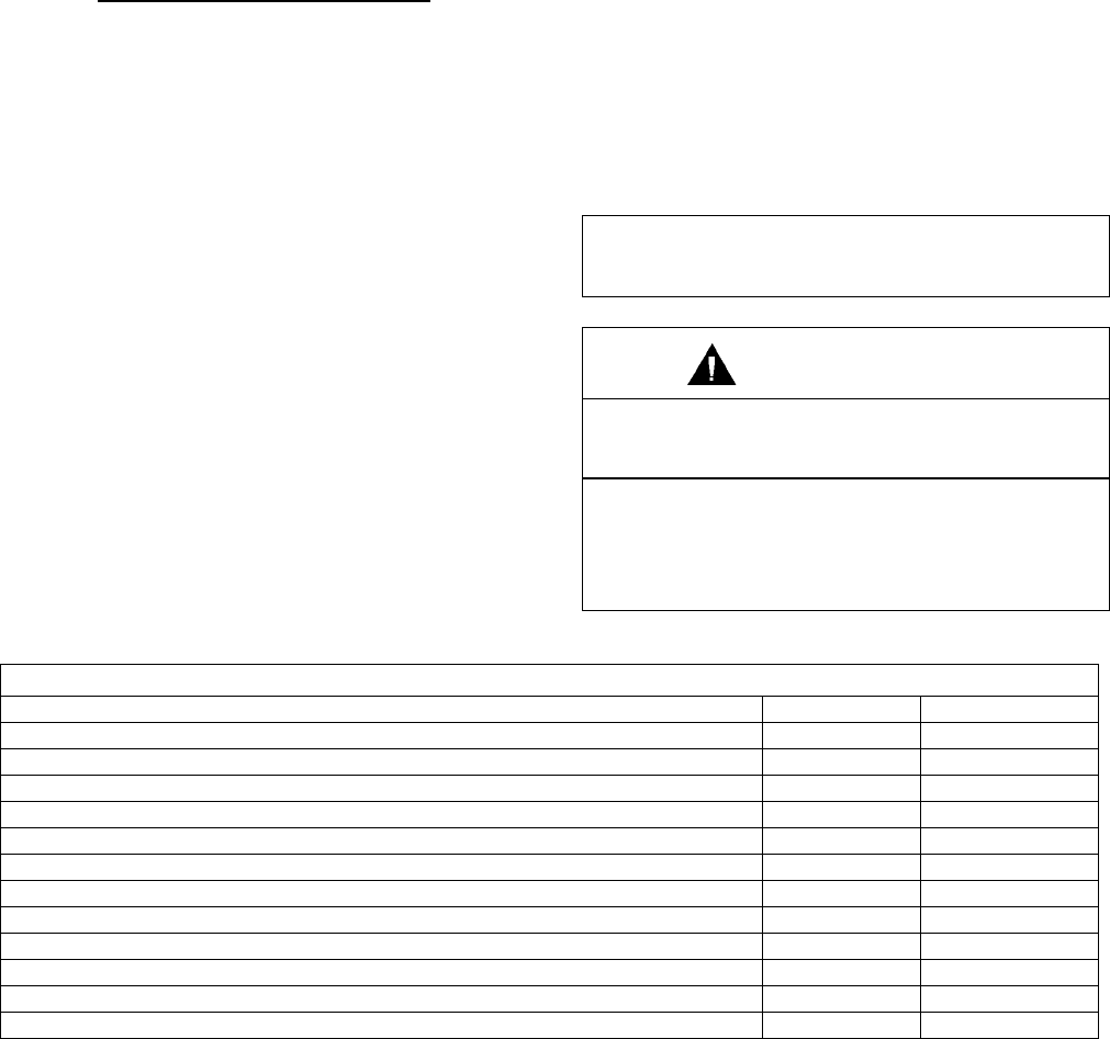
LIST OF PART ILLUSTRATIONS
TITLE FIGURE No. PAGE No.
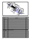
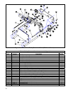
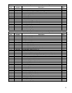
Hoist Drum, Drum Frame, Gearcase, Motor, Rope Guide, and Limit Switch 9-1 30
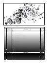
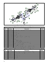
Hoist Gearing 9-2 32
Motor Driven Trolley Frame and Drive 9-3 34
Lower Block Assembly 9-4 36
Upper Block Assembly 9-5 38
“B” Frame Rope and Dead End Assembly 9-6 39
“C” Frame Rope and Dead End Assembly 9-7 40
Block Operated Limit Switch Assembly 9-8 40
Rope Guide Assembly 9-9 42
Hoist Motor Brake 9-10 43, 44
“B” Trolley Drive Gear Reducer 9-11 45
“C” Trolley Drive Gear Reducer 9-12 46