


20
(4) Disconnect the wiring and conduit from
the motor junction box.
(5) Provide a means to support the hoist
motor. The hoist motor weighs approx-
imately 250 lbs. And must be held level
while removing and installing.
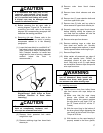
(6) Once the motor is properly supported,
remove the hardware fastening it to the
gear case. Carefully withdraw the motor
horizontally straight out from the gear
case. Do not tip or move the motor from
side to side.
(7) Replace the motor shaft seal using an
appropriate seal driver. It is
recommended that a new seal be
installed each time the motor is removed
from the case.
IMPORTANT!
(8) Before installing the motor, pack the gear
teeth with MPG grease (Paragraph 4-7)
and wrap the gear teeth with a number of
layers of Teflon tape to protect the seal
lip from being damaged by the gear
teeth. Coat the seal lip and the motor
shaft with MPG grease.
NOTICE
Failure to use a factory replacement seal
will cause premature seal failure due to
specific lip material requirements that
must be met.
(9) Install the motor to the gear case. The
motor shaft must be in line with the seal
bore and perpendicular to the mounting
surface before attempting to insert the
shaft through the seal. The motor shaft
must remain horizontal and not rock up
and down or side-to-side while installing
the motor or seal damage will occur. It
may be necessary to rotate the rope
drum slightly to align the gear teeth to
mesh with the teeth on the motor shaft.
Ensure that the motor seats properly into
the rabbet fit machined in the gear case.
Fasten the motor to the gear case.
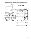
(10) Reconnect the conduit and power
leads to the motor. See Section VIII
and refer to the specific wiring
diagrams shipped with your hoist.
(11) Refill gear case with lubricant per
Section IV, Paragraph 4-2.
(12) Test hoist to ensure proper operation
per Section V, Paragraph 5-13.
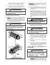
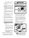
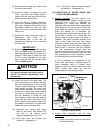
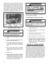
5-10. INSPECTION OF MOTOR BRAKE AND
ACTUATING MECHANISM.
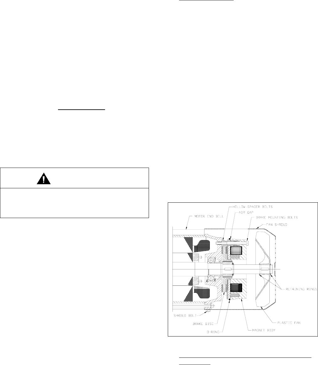
a) General Operation
. The hoist brake is an
electro-magnetically released, spring set non-
adjustable brake. Torque is generated by
compressing a friction disk between the
stationary motor end bell and the spring loaded
brake armature. The friction disk is fixed to the
motor shaft and rotates with the motor shaft.
When the magnet coil is energized, the
armature plate is pulled across the air gap. The
friction disk is carried by a splined hub that
permits axial movement when the brake is
released. This axial movement releases both
sides of the friction disk from their mating
stationary surfaces and allows the friction disk
to rotate freely when the brake is energized.
When power is removed from the magnetic
coil, the compression springs push the
armature against the friction disk and the other
side of the friction disk against the motor end
bell generating the torque necessary to stop
the hoist machinery and hold the load.
It will be necessary to compensate for the
friction disk wear when a greater amount of
hook movement (drift) is noticed when
stopping. There is no torque adjustment of the
brake. Friction disk wear can only be
compensated for by resetting air gap.
Figure 5-9. Motor Brake.
b) Friction Disk Inspection and Air Gap
Adjustment.
(1) Lower hook block to the floor and relieve
all load from ropes.