25
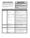
SECTION VI – TROUBLE SHOOTING
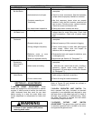
TROUBLE PROBABLE CAUSE REMEDY
6-4 Hook Will Lower,
But Not Raise.
a. Excessive load.
b. Hoist electrical circuit open.
c. Contactor assembly not
functioning.
d. Up, down button inoperative.
a. Reduce loading to rated load of hoist as shown on
nameplate.
b. Check for loose connections. See that necessary
jumper wires are properly installed on contactor.
c. See that necessary jumper wires are properly
installed. Verify that the contactor armatures are
free to move. If binding occurs, replace contactor.
Check for burned out contactor coils.
d. Check push button contacts and wires.
6-5 Hoist Will Not
Lift Rated Load.
a. Low voltage.
a. See that the power supply current is the same
voltage listed on motor data plate. Check hoist
motor connections. Check size of power supply
lines.
6-6 Hoist Motor
Overheats.
a. Excessive load.
b. Excessive duty-cycle.
c. Wrong voltage or frequency.
d. Defective motor or worn
bearings in hoist frame.
e. Brake not adjusted correctly.
a. Reduce loading to rated load as shown on
nameplate.
b. Reduce frequency of lifts or amount of jogging.
c. Check current rating on motor data plate against
power supply. Check hoist and inspect for
defective, worn or damaged parts.
d. Disassemble hoist and inspect for defective, worn
or damaged parts.
e. Adjust brake per Section VII, Paragraph 7-1.
6-7 Load Drifts
Excessively
When Hoist is
Stopped.
a. Excessive Load.
b. Motor brake not holding.
a. Reduce loading to rated load as shown on
nameplate.
b. With No Load, check hoist for drift. If drifting is
excessive, inspect motor brake (Section V,
Paragraph 5-10) and adjust as outlined in Section
VII, Paragraph 7-1.
6-8 Hoist Operates
Intermittently.
a. Collectors make poor contact.
b.
Loose connections.
a. Check collectors for free movement of spring arm,
weak spring or electrical connections.
b. Check all wiring for loose connections.
SECTION VII – ADJUSTMENTS
7-1. MOTOR BRAKE ADJUSTMENT. These
brakes are designed so that adjustment is seldom
required. If, after a period of service, the load hook
“drifts” downward more than usual for your hoist
before coming to a stop, the motor brake may
require adjustment to compensate for brake disc
wear.
WARNING
Check to be certain main power switch
is locked in open position (OFF) before
removing brake cover.
Refer to Figure 5-9 and proceed as outlined in
Section V, Paragraph 5-10.
7-2. BLOCK OPERATED LIMIT SWITCH. The
block operated limit stop, furnished as standard
equipment, is non-adjustable and designed to stop
the lower block at the safest high point of travel to
eliminate any possibility of double-blocking. When
the safest high point is reached, the limit switch
automatically stops hook travel.
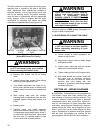
7-3. GEARED ROTARY LIMIT SWITCH
ADJUSTMENT. The geared rotary type limit switch
is standard equipment and is located on the drum
end opposite the gearcase end.


