


18
torque the remaining two (2) rope
clamps in sequence to 50 ft-lbs.
(2) With all personnel clear of hoist – TURN
ON POWER.
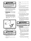
(3) Operate hoist “UP” guiding six (6) wraps
of new rope into drum grooves with
gloved hand.
(3) Re-install rope guide over rope in rope
drum grooves as shown in Figure 5-3.
and outlined in Section V, Paragraph 5-6.
Continue lubricating as rope is spooled
onto the drum until about 28’-0” remain
unwound.
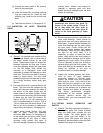
(7) With outer lower block covers removed,
thread the wire rope through the sheaves
of the upper and lower block as shown in
Figure 5-6.
(8) Attach swaged rope end to the dead end
anchor pin fastening cotter pins or
retaining rings as required.
(9) Replace the lower block sheave covers.
(10) Lubricate cable per Paragraph 4-3.
See Figure 9-5 (“B” Frame components) for
lower block parts with 7/16” diameter wire
rope.
See Figure 9-5 (“C” Frame components) for
lower block parts with 9/16” diameter wire
rope.
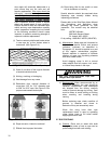
c) Checking for and removal of rope twisting.
(1) To remove rope twist in four part single
reeved hoists:
(a) Observe direction block tends to
rotate.
(b) Lower the block to a low position
and TURN OFF (lock out) POWER.
(c) Remove swaged fitting from anchor
pin and rotate rope several turns in
a direction tending to correct block
rotation.
(d) TURN ON POWER; raise and
lower the block several times to
feed the correcting twist in the rope
through the reeving.
5-8. INSPECTION OF ROPE DRUM AND SHAFT.
a) To remove the rope drum, remove the rope
guide and hoisting cable, as outlined in Section
V, Paragraphs 5-5 and 5-7.c. respectively.
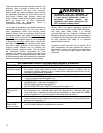
WARNING
The hoist must be removed from service
and placed on the ground for any
maintenance that requires removal of
the output shaft assembly or drum.
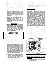
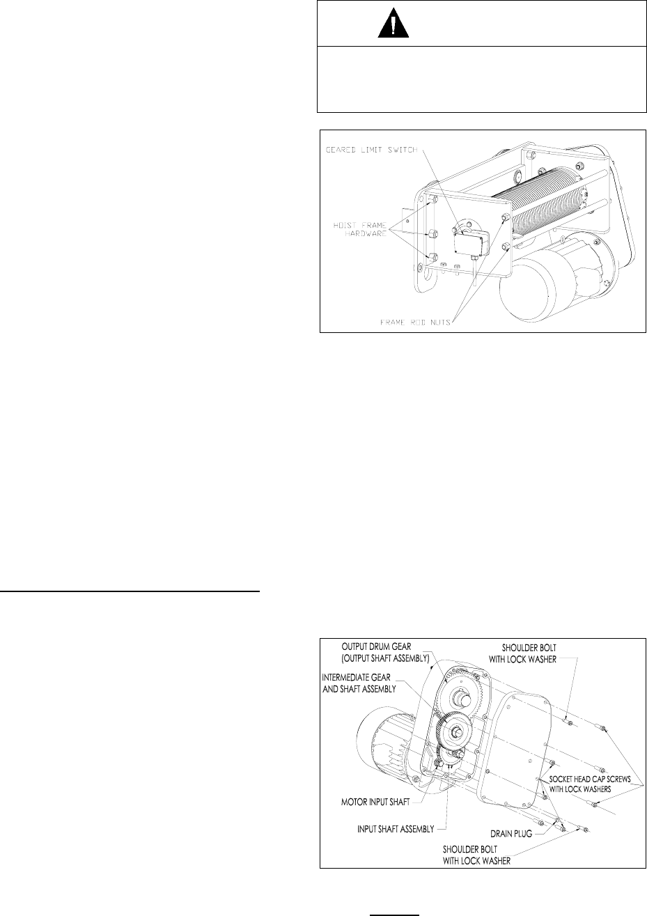
Figure 5-7. Drum Frame & Geared Limit Switch.
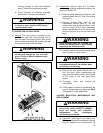
b) Remove the Geared Limit Switch or disconnect
the wires so that the electrical cable will not
inhibit removal of the drum. (See Figure 5-7).
c) Remove the unit from service, place it on the
ground, and provide adequate means to
support the drum before removing the frame
rod nuts at the outboard drum frame end
(Figure 5-7). The hardware attaching the drum
frame to the hoist and trolley frame may then
be removed.
d) Keeping the drum level, remove the drum from
the splined output shaft at the gear case end.
5-9. INSPECTION OF HOIST GEARING.
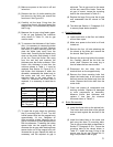
Figure 5-8. Hoist Gear Case Assembly.
a) General
. The hoist gear case is a triple
reduction splash lubricated vertically split
cast aluminum case and cover. The first
two high-speed reductions are helical and
the third low speed output reduction is