


26
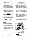
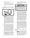
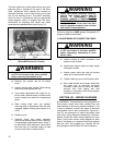
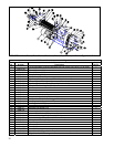
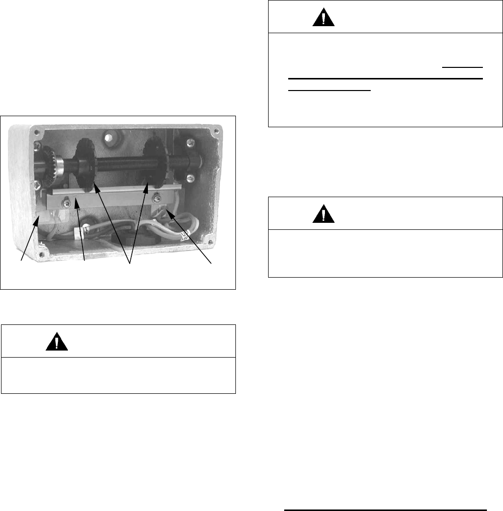
This limit switch has a rotary screw driven by a gear
reduction that is coupled to the end of the drum
shaft. Adjustment discs operate the contacts of
separate switches, one for the hoisting circuit and
one for the lowering circuit. The switch assembly
must be wired in accordance with the appropriate
wiring diagram, which is shipped with the hoist.
Instructions for adjusting limit switch are inside
cover and are repeated below (see Figure 7-2).
SWITCH LOCKING ADJUSTMENT SWITCH
PLATE DISC
Figure 7-2. Screw-Type Limit Switch Adjustment
(Wires Not Shown For Clarity.)
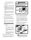
WARNING
Be certain that electrical power supply
is OFF and locked in the open position
before removing limit switch cover.
a) Remove four screws and lift off switch
cover.
b) Loosen locking plate screws. Slide locking
plate away from adjustment disc.
c) Turn proper adjustment disc (right for up,
left for down) toward switch to reduce hook
travel or away from switch to increase hook
travel.
d) Slide locking plate back into position
ensuring slots on adjustment discs are fully
engaged, tighten locking plate screws to 4
in-lbs.
e) Replace cover.
f) Carefully check limit switch operation
without load before placing hoist in service.
If misadjusted, repeat steps above. Allow 3”
for hook drift in both directions. Never allow
less than two (2) complete wraps of rope
on drum with hook in lowest position.
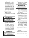
WARNING
Check limit switch operation carefully,
without load, before placing hoist in
service. If misadjusted, SEVERE
DAMAGE AND/OR A DROPPED LOAD
COULD RESULT. Allow 3” for hook drift
in both directions. Never allow less than
two (2) complete wraps of rope on drum
with hook in lowest position.
Provide a light film of MPG grease (Paragraph 4-7)
on gear of both limit switches.
7-4. SHORTENING OF PUSHBUTTON CABLE.
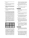
WARNING
Be certain that electrical power supply
is OFF and locked in the open position
before attempting shortening of push
button cable.
a) Loosen screws at cable connectors and
clamps at top of cable.
b) Adjust steel support cable to proper length
and tighten screws.
c) Loosen upper cable grip and pull excess
cable into connection box at hoist.
d) Tighten cable grip and cut off excess cable.
e) Strip cable sheath and connect wires with
the same type of terminals previously
furnished (care must be taken to match
previous wire color coding with wire
markers in accordance with wiring diagram
furnished with hoist.)
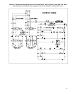
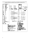
SECTION VIII – WIRING DIAGRAMS
8-1. GENERAL. Comprehensive wiring diagrams for
Yale electric hoists have been omitted from this
book because of the many possible variations. This
is due to different currents and types of electrical
components used in their construction. Figures 8-1
and 8-2 are examples of typical two-speed hoist
and trolley wiring diagrams respectively. However,
please consult the exact wiring diagrams for your
hoist. A print of the correct wiring diagram for each
hoist is furnished as a separate insert and shipped
with the hoist. We suggest you carefully file the
wiring diagram with this book for future reference.