


6
TROUBLESHOOTING
6 - 1
1
OVERVIEW
2
SYSTEM
CONFIGURATION
3
SPECIFICATIONS
4
FUNCTIONS
5
SETTINGS AND
PROCEDURES BEFORE
OPERATION
6
TROUBLESHOOTINGAPPENDIX
CHAPTER 6 TROUBLESHOOTING
This chapter explains description, cause investigation, and corrective action of an error
when using the safety relay module.
To increase system reliability, starting the system early in the case of a failure is important
as well as using the highly-reliable devices.
The following is the basic three points that should be noted when performing
troubleshooting to find a failure cause, take corrective action against it, and start the
system early.
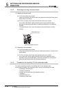
(1) Visual check
Check the following points.
1) Machine status (stop status, operating status)
2) Status of safety relay module power supplies
3) External device status
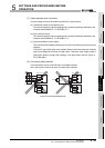
4) Module mounting status
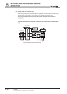
5) Wiring status (safety input line, power supply cable, CC-Link dedicated cable,
extension cable)
6) Indication status of various indicators (POW, PW, ERR., K0, K1, Z, X0, X1,
L RUN, SD, RD, L ERR.)
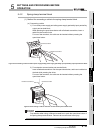
7) Setting status of various setting switches
After checking from 1) to 7), monitor PLC diagnostics, module operating status, or
program contents with GX Developer.
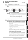
(2) Failure check
An failure is divided into two categories as shown below.
(a) Safety-related failure
1) Whether the safety input is ON
2) Whether the safety input does not change at start-up
3) Whether the external device connected to off check remains OFF until start-up
4) Whether K0 and K1 LEDs are both OFF before start-up
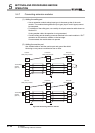
(b) Monitor-related failure
Check how a failure changes by the following operations.
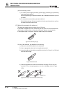
1) Switch the RUN/STOP/RESET switch on the programmable controller to
“STOP”.
2) Switch the RUN/STOP/RESET switch on the programmable controller to
“RESET”.
3) Power ON/OFF the monitor sides of the safety relay module and
programmable controller.