5
SETTINGS AND PROCEDURES BEFORE
OPERATION
5.4 Wiring
5.4.5 Connecting with CC-Link dedicated cables
5 - 34
1
OVERVIEW
2
SYSTEM
CONFIGURATION
3
SPECIFICATIONS
4
FUNCTIONS
5
SETTINGS AND
PROCEDURES BEFORE
OPERATION
6
TROUBLESHOOTINGAPPENDIX
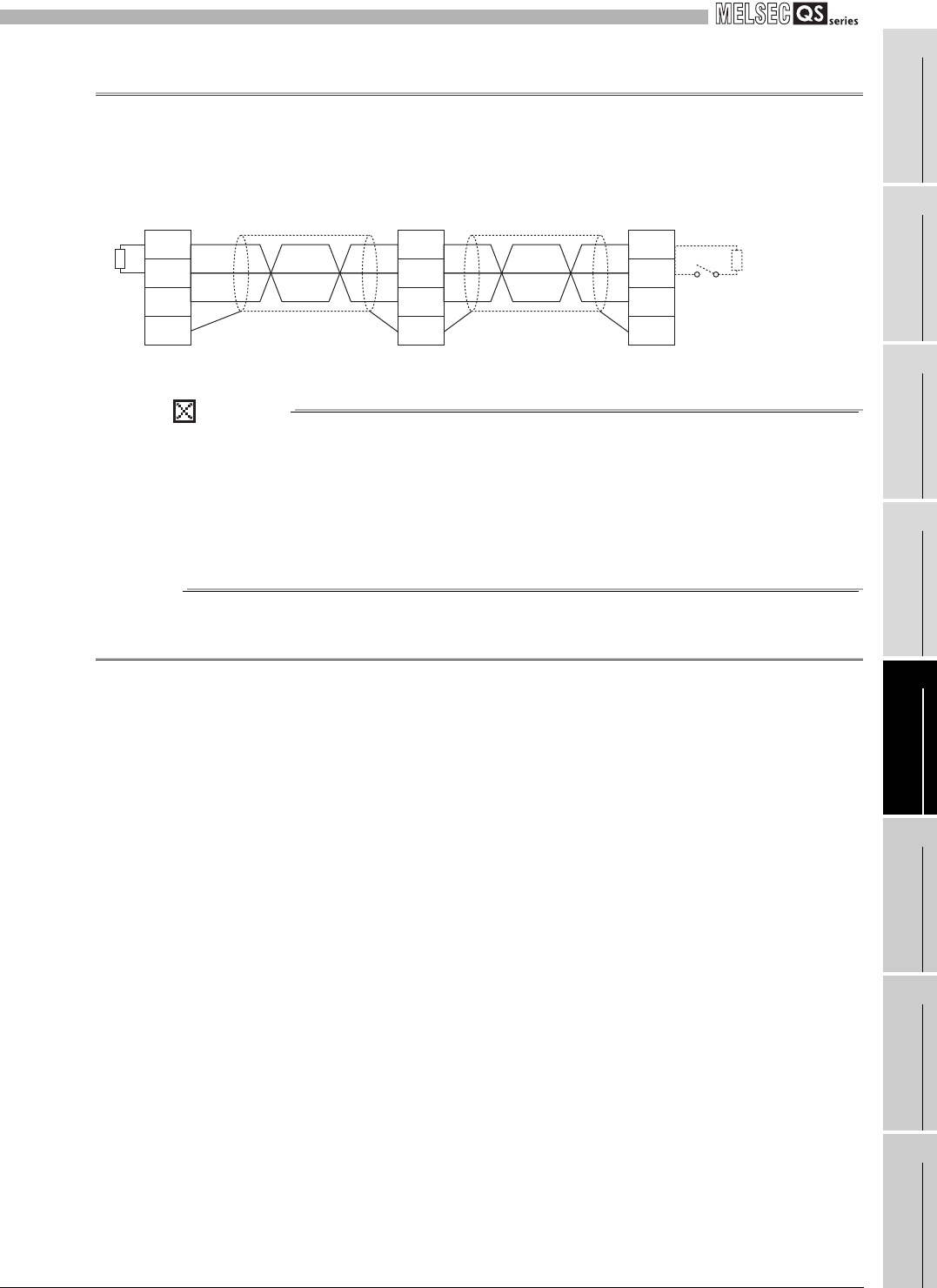
5.4.5 Connecting with CC-Link dedicated cables
Figure 5.25 shows how safety relay modules are connected with CC-Link dedicated
cables.
Figure 5.25 Connecting with CC-Link dedicated cables
(1) Connect the shielded wire of the CC-Link dedicated cable to SLD terminals of
each module, and ground the both ends to the protective ground conductor
via FG terminals.
The SLD and FG terminals are connected inside the module.
(2) Always connect terminating resistor to both ends of the module on data link.
Connect terminating resistor between DA and DB terminals.
5.4.6 Precautions for wiring power supply
When wiring to the power supply of safety relay module, take care of the following points.
• Cable length of the module power supply must be within 10m (32.81 feet) or less.
• The power supply to be connected to the safety relay module must meet the
following conditions.
1) The switching power supply complies with the EMC Directive, EN50178,
EN60950-1 standard, and NEC CLASS2.
2) SELV (Safety Extra Low Voltage): Reinforced insulation from hazardous
potential area (48V or more) is provided.
3) The power supply complies with the LVD Directive.
4) The output voltage specification value is from 20.4 to 26.4VDC (ripple ratio
within 5%).
• Use respective power supply for the module power supply and the safety power
supply in order to obtain safety approval.
• Operating voltage range may differ for each module. Be careful with that when
sharing the power supply with other Q/QS series modules.
• The safety relay module may consume excessive current due to a failure. If this
occurs, the DC power supply connected to the safety power supply part (+24V
(SAFETY) and 24G (SAFETY) terminals) of the module detects an overcurrent
and may shut off the output.
To the DC power supply connected to the safety relay module, connect only the
equipment and the devices that will not affect the system even if they are
simultaneously stopped due to power-off.
SLD
DG
DB
DA
SLD
DG
DB
DA
SLD
DG
DB
DA
Terminating
resistor
Turn ON the CC-Link
terminating resistor
setting switch "LT".
CC-Link
safety relay module
CC-Link
safety relay module
(Yellow)
(White)
(Blue)
Master module


