5 - 27
5.4 Wiring
5.4.1 Precautions for safety devices and wiring
5
SETTINGS AND PROCEDURES BEFORE
OPERATION
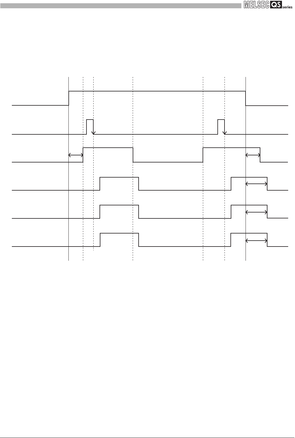
(d) Time chart
Figure 5.16 shows the operation timing of each device when safety shutdown is
executed by the main unit in the system where a light curtain is connected to the
extension module.
Figure 5.16 Operation time chart when a light curtain is connected
* 1: Confirm that the light curtain has started, and then turn on the start-up switch of the extension
module.
* 2: Light curtain start-up time differs depending on the type of the light curtain.
* 3: Light curtain stop time differs depending on the type of the light curtain.
* 4: As for safety output response time, time until output on is 50ms or less and time until output off is
20ms or less.
For details, refer to Section 3.4.
* 5: Safety outputs are turned off after the light curtain stops. Configure the system considering the
time described at *3 and *4.
Safety output
*4
(extension module Z20-Z21)
Safety output
*4
(extension module Z10-Z11)
Safety output
*4
(extension module Z00-Z01)
Light curtain
(extension module X0-X1)
Start-up switch (M mode)
(extension module XS0-XS1)
Start-up switch
turned on again
Blocked status
terminated
Beams blocked
*5
*5
*5
*3
*2
OFF
ON
*1*1
Emergency stop
(released status)
Light curtain
(beams blocked status)
Start-up switch
turned on
Light curtain
started
Emergency stop
(activated status)
Emergency
stop activated
Emergency
stop released
Emergency stop switch
(main module X0-X1)


