


2
SYSTEM CONFIGURATION
2.2 Applicable Systems
2 - 2
1
OVERVIEW
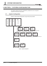
2
SYSTEM
CONFIGURATION
3
SPECIFICATIONS
4
FUNCTIONS
5
SETTINGS AND
PROCEDURES BEFORE
OPERATION
6
TROUBLESHOOTINGAPPENDIX
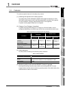
2.2 Applicable Systems
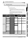
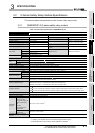
(1) Mountable modules, the number of mountable modules, and mountable base
units
(a) Q series safety relay module
1) When mounting to CPU module
The following table shows the mountable CPU modules, the number of
mountable modules, and mountable base units of the Q series safety relay
module.
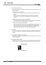
Shortage of power capacity may occur depending on the combination with
other mounted modules or the number of mounted modules.
When mounting modules, pay attention to the power capacity.
When shortage of power capacity occurs, review the combination of modules
to be mounted.
: Mountable, : Not mountable
* 1: Limited within the range of the number of I/O points for the CPU module.
* 2: Mountable on any I/O slots of the mountable base unit.
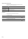
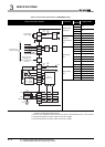
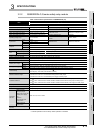
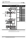
Table 2.1 Applicable modules and the number of mountable modules
Mountable CPU module
Number of
mountable
modules
*1
Mountable base unit
*2
CPU type CPU model Main base unit
Extension base
unit
Programmable
controller CPU
Basic model QCPU
Q00JCPU Up to 8
Q00CPU
Up to 12
Q01CPU
High Performance
model QCPU
Q02(H)CPU
Up to 32
Q06HCPU
Q12HCPU
Q25HCPU
Process CPU
Q02PHCPU
Up to 32
Q06PHCPU
Q12PHCPU
Q25PHCPU
Universal model
QCPU
Q00UJCPU Up to 8
Q00UCPU
Up to 12
Q01UCPU
Q02UCPU Up to 18
Q03UD(E)CPU
Up to 32
Q04UD(E)HCPU
Q06UD(E)HCPU
Q10UD(E)HCPU
Q13UD(E)HCPU
Q20UD(E)HCPU
Q26UD(E)HCPU
Q50UDEHCPU
Q100UDEHCPU
Redundant CPU
Q12PRHCPU
Up to 31
Q25PRHCPU
C Controller module
Q06CCPU-V
Up to 32
Q06CCPU-V-B
Q12DCCPU-V