


2 - 3
2.2 Applicable Systems
2
SYSTEM CONFIGURATION
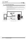
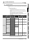
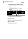
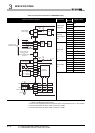
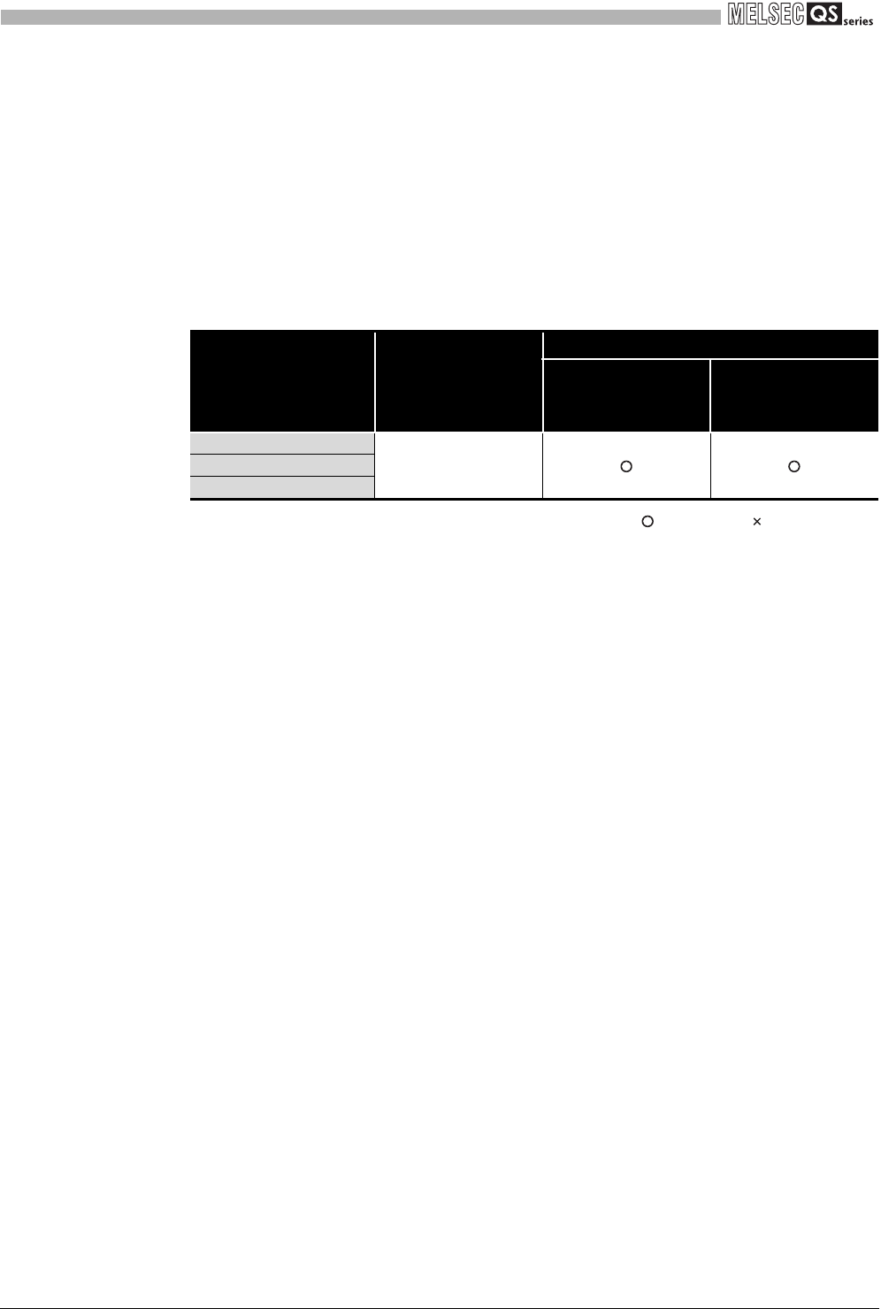
2) When mounting to remote I/O station in MELSECNET/H connection
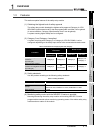
The following table shows the mountable network modules, the number of
mountable modules, and mountable base units of the Q series safety relay
module.
Shortage of power capacity may occur depending on the combination with
other mounted modules or the number of mounted modules.
When mounting modules, pay attention to the power capacity.
When shortage of power capacity occurs, review the combination of modules
to be mounted.
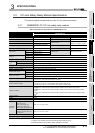
: Mountable, : Not mountable
* 1: Limited within the range of the number of I/O points for the network module.
* 2: Mountable on any I/O slots of the mountable base unit.
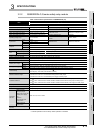
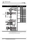
(b) CC-Link safety relay module
The CC-Link safety relay module is used as remote I/O station.
For system configuration of the CC-Link system, refer to the Control &
Communication Link System Master/Local Module User's Manual.
(c) Extension safety relay module
Up to three extension safety relay modules can be added to a Q series safety
relay module or CC-Link safety relay module.
For extension method, refer to Section 5.3.
Table 2.2 Network modules and the number of mountable modules
Mountable network
module
Number of
mountable
modules
*1
Mountable base unit
*2
Main base unit on
remote I/O station
Extension base unit
on remote I/O
station
QJ72LP25-25
Up to 32
QJ72LP25G
QJ72BR15