


37
Leica VT1200 and VT1200S – Microtome
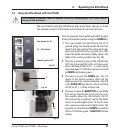
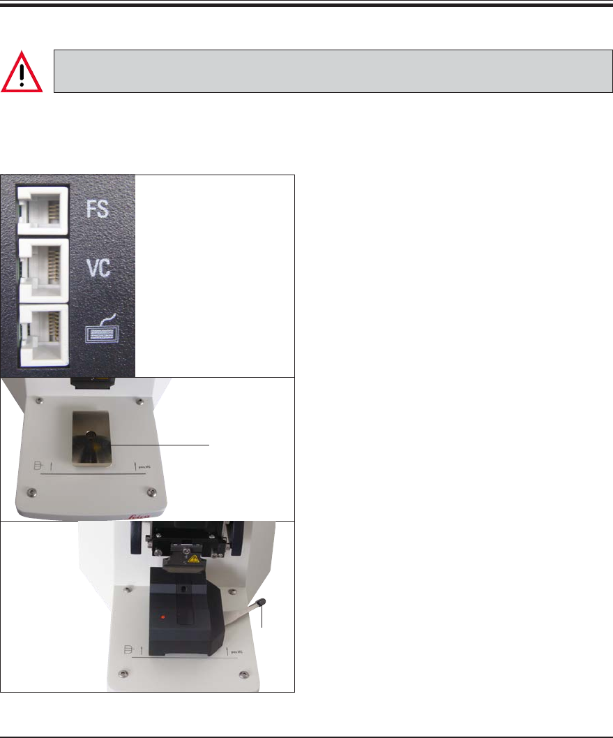
6.1 Using the VibroCheck with the VT1200
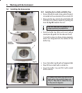
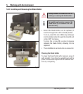
Prior to assembly, the dovetail guide (3) is brought
down to the lowest position using the DOWN key!
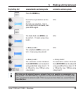
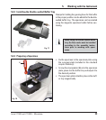
1. The user installs the VibroCheck: the VC is
pushed along the dovetail guide (3) past the
mark on the base plate of the instrument (rear
stop) and clamped firmly using the lever (15).
Insert the blade and clamp tightly. Return the
blade to the cutting position (see Fig. 20).
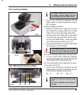
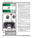
2. Plug the connecting plug of the VibroCheck
(VC) into the socket (2) on the left side panel.
Short red flash of LED on VC --> control panel
acknowledges VC. LED then remains red. LED
in DOWN key flashes green.
(2) – VibroCheck
Fig. 23
Control panel for VT
Foot switch for VT
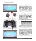
The following instructions must be adhered to exactly. Noncompliance can cause serious
damage to the instrument.
Fig. 25
3
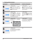
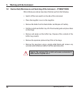
3. The user presses the DOWN key. The VC
moves to the bottom position, after that the
blade moves to the rearmost position – the LED
in the RUN/STOP key flashes. Short red flash
of LED on VC --> it then remains red.
4. The user presses the RUN/STOP key: the blade
first moves towards the front (into the posi-
tion exactly above the VibroCheck); the VC
then moves into a position in which the blade
partly covers the light barrier. (If the VC does
not receive any signal via the light barrier, the
operation is canceled and DOWN is enabled.)
LED on VC flashes green – RUN/STOP flashes
yellow.
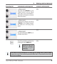
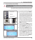
We recommend using the VibroCheck after each blade change to check
the optimum position of the blade and minimize the vertical vibration.
6. Operating the VibroCheck
15
Fig. 24