27
5. Assembly
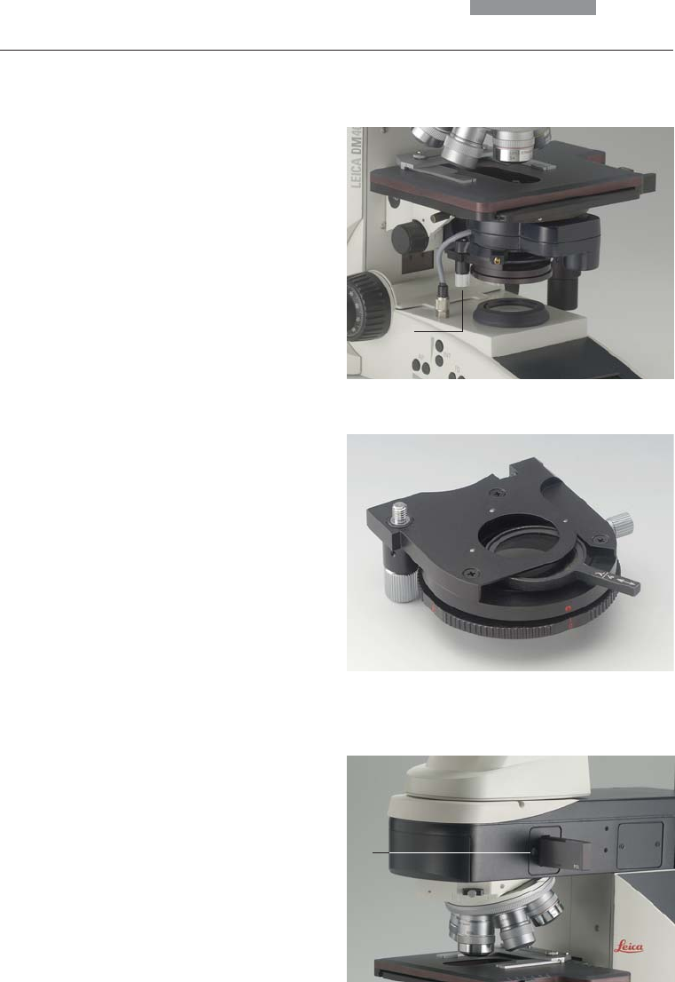
ICT/P transmitted light polarizer
• Using the left clamping screw, fasten the ICT/P
transmitted light polarizer to the underside of
the condenser holder (Fig. 27).
• Make sure that the red index point on the front
of the polarizer is aligned with 0.
• If necessary, insert the compensators (λ- and
λ/4 plates) into the polarizer’s receptacle
(Fig. 28).
Incident light polarizers:
R/P polarizer, rotating polarizer
L/ICR, R/ICR polarizer
• Remove the plug cap on the right side of the
incident light axis (Fig. 29).
• Insert the polarizer into the receptacle until it
latches in place.
Motorized polarizer
• A motorized polarizer is already installed and
ready for operation in the DIC condenser.
Transmitted light and incident light analyzer
Fig. 27 Assembly of the ICT/P transmitted light polarizer
1 Clamping screw
Fig. 28 Inserting the compensators
Fig. 29 Inserting the polarizer
1 The plug cap is replaced with the polarizer.
1
1


