


39
F
O
O
T
R
E
S
T
PROCEDURE 8
A
N
T
I
T
I
P
P
E
R
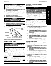
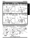
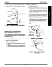
FOOTREST/ANTI-TIPPER
1-1/2 to 2-inch clearance
Anti-tipper
Extension
Release
Buttons
Anti-tipper
Bar
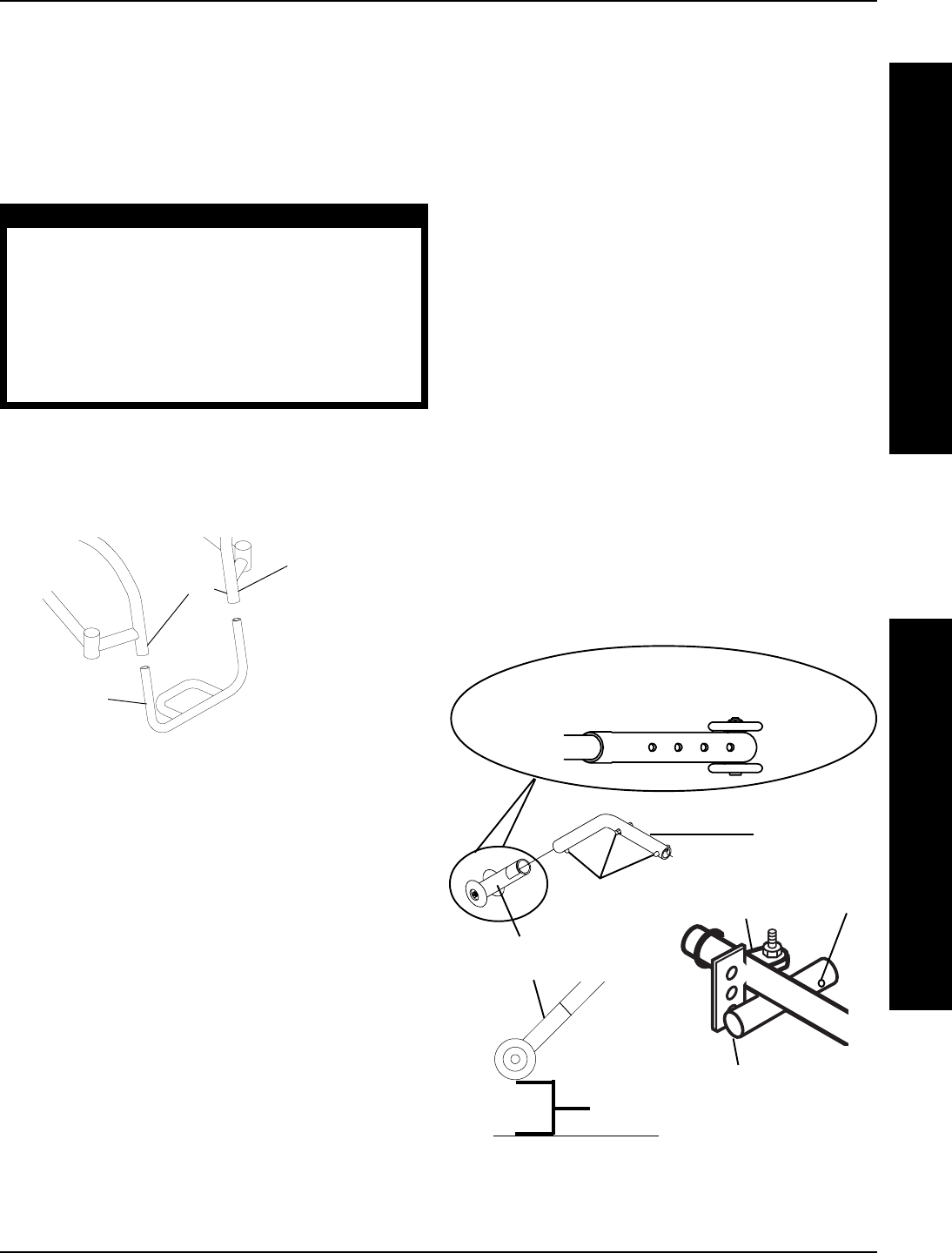
FIGURE 3 - ANTI-TIPPER ADJUSTMENT/REPLACEMENT
Anti-tipper Socket
Camber
Clamp
DETAIL "A" - ANTI-TIPPER
ADJUSTMENT HOLES
Mounting
Hole
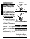
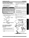
ANTI-TIPPER REPLACEMENT/
ADJUSTMENT (FIGURE 3)
Replacement
1. Press in the two (2) push pins that secure the EXIST-
ING anti-tipper bar to the anti-tipper socket.
2. Remove the anti-tipper bar from the anti-tipper
socket.
4. Insert the NEW anti-tipper bar into the anti-tipper
socket.
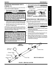
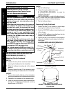
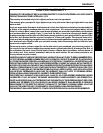
ADJUSTING/REPLACING RIGID
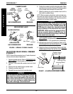
TUBULAR FOOTREST (FIGURE 2)
1. Loosen the two (2) Allen Screws that secure the
footrest to the wheelchair frame.
If Replacing the Footrest:
1. Remove EXISTING and install NEW footrest.
Footrest
Wheelchair
Frame
Allen
Screws
FIGURE 2 - ADJUSTING/REPLACING STANDARD
FOOTREST
WARNING
The standard footrest has an open hoop. A
footplate cover is recommended for wheelchair
users that have leg spasticity or whose feet have
a possibility of falling through the footrest hoop. A
calf strap is provided with each wheelchair to
prevent the feet from slipping backwards off of
the footrest. Be sure the calf strap is secure when
using the wheelchair.
If Replacing or Adjusting the Footrest:
1. Position NEW/EXISTING footrest to desired height.
2. Tighten the two (2) Allen Screws that secure the
footrest to the wheelchair frame.
5. Ensure the push pins are fully engaged in the
mounting holes of the anti-tipper socket.
6. Repeat STEPS 1-5 for the opposite anti-tipper if
necessary.
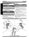
Adjustment
NOTE: If the rear wheel size is changed or the position of
the adjustable axle camber bar is changed, the anti-tip-
pers MUST be readjusted to maintain a 1-1/2 to 2-inch
clearance between the bottom of anti-tipper wheels and
floor.
1. Press the push pin securing the anti-tipper exten-
sion to the anti-tipper bar.
2. Position the anti-tipper extension to one (1) of four (4)
mounting holes which allow a 1-1/2 to 2-inch clear-
ance of the wheels to the floor.
NOTE: A 1-1/2 to 2-inch clearance between the bot-
tom of the anti-tipper wheels and the floor must be
maintained.
8. Ensure the push pin is fully engaged in the anti-
tipper extension mounting hole.
9. Repeat procedure for opposite anti-tipper if nec-
essary.