


32
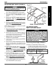
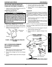
FIGURE 11 - ADJUSTING WHEELBASE LENGTH
WHEELSPROCEDURE 7
W
H
E
E
L
S
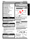
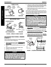
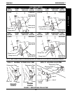
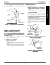
Clamp
Axle Tube -
Rotates Up and
Down
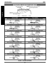
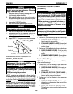
FIGURE 10 - ADJUSTING TOE IN/TOE OUT
NOTE: Rear wheels removed from the drawings for clar-
ity, There is no need to remove rear wheels from the
wheelchair during adjustment.
4. Measure the distance between the center lines at the
rear and front of the rear wheels at approximately 12-
inches from the ground/floor. Refer to DETERMIN-
ING TOE IN/TOE OUT in this procedure of the manual.
5. Repeat STEPS 1-4 until the toe in/toe out measurement
is less than 1/2-inch (0 + 1/4-inch for maximum rollability).
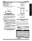
NOTE: Marks on the telescoping tubes have been pro-
vided to ensure the telescoping tubes are aligned with
each other. The performance of the wheelchair will be
affected if the two (2) telescoping tubes are not adjusted
to the same position. Refer to FIGURE 11.
WARNING
QUICK RELEASE LEVERS - Make sure the quick re-
lease levers are pointing towards the inside of the
wheelchair and is in the CLOSED position BEFORE
using the wheelchair, otherwise personal injury or
damage to the wheelchair may result.
STANDARD - Make sure the hex screws and lock-
nuts are securely tightened BEFORE using the
wheelchair, otherwise personal injury or damage
to the wheelchair may result.
CAUTION
Do not close the quick-release levers or tighten
the hex screws and locknuts without telescoping
tubes int he receiver tubes. Damage to the re-
ceiver tubes will occur.
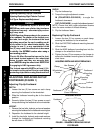
3. Close both receiver tube clamps. Refer to
OPEN-
ING/CLOSING CLAMPS in this procedure of the
manual.
4. Roll the wheelchair before using to make sure there
is no excessive drag to either side.
NOTE: If drag to either side occurs, refer to DETERMIN-
ING/ADJUSTING TOE IN/TOE OUT in this procedure of
the manual.
Receiver Tube
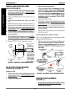
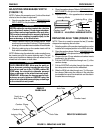
ADJUSTING WHEELBASE LENGTH
(FIGURE 11)
WARNING
Always perform this procedure in the presence
of an assistant. The position of the footrest, cam-
ber tube, back angle, the tautness of the back
upholstery as well as the user's condition are di-
rectly related to the wheelchairs stability. Any
change to one (1) or any combination of the
five (5) may cause the wheelchair to decrease
in stability. Use EXTREME caution when using a
NEW seating position.
1. Open both receiver tube clamps. Refer to
OPENING/
CLOSING CLAMPS in this procedure of the manual.
WARNING
Telescoping tubes have two types of marks -
"0" and "X" (DETAIL "A"). "X" marks are provided
to indicate that the telescoping tube has been
extended too far. DO NOT adjust the telescop-
ing tubes so any "X" marks are showing. Other-
wise, injury or damage may occur.
2. Perform one (1) of the following:
A. PULL telescoping tubes out of receiver tubes
to LENGTHEN THE WHEELBASE, increase
stability and maintain standard maneuverabil-
ity of the wheelchair.
B. PUSH telescoping tubes into receiver tubes
to SHORTEN THE WHEELBASE, increase
the maneuverability, distribute additional weight
onto the rear wheels and decrease the stabil-
ity of the wheelchair.
DETAIL "A" -
TELESCOPING
TUBE MARKS
"X" Marks
"0" Marks