


25
ADJUSTING SEAT WIDTH (FIGURE 4)
WARNING
The following procedure should only be per-
formed by a qualified technician.
1. Remove the EXISTING footplate from the wheel-
chair. Refer to PROCEDURE 8 of this manual.
2. Remove the EXISTING back upholstery from the
wheelchair. Refer to PROCEDURE 4 of this
manual.
3. Remove the EXISTING spreader bar from the
wheelchair. Refer to
REPLACING THE
SPREADER BAR in PROCEDURE 4 of this
manual.
4. Remove the EXISTING seat pan from the wheel-
chair. Refer to
REPLACING SEAT PAN in this pro-
cedure of the manual.
NOTE: Retain the attachment hardware for installa-
tion of the NEW seat pan.
5. Remove the axle tube from the wheelchair. Refer
to REPLACING AXLE TUBE in PROCEDURE 7
of this manual.
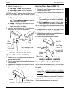
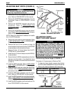
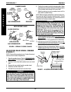
6. Remove the four (4) hex screws and eight (8)
coved washers that secure the two (2) EXISTING
crossmembers to the wheelchair frame.
7. Remove the four (4) frame clamps from the EX-
ISTING two (2) crossmembers.
8. Install the four (4) frame clamps onto the NEW (2)
crossmembers.
9. Secure the two (2) NEW crossmembers to the front
and rear mounting holes in the wheelchair frame
with the hex screws and coved washers removed
in STEP 5.
10. Install the NEW axle tube. Refer to
REPLACING
AXLE TUBE in PROCEDURE 7 of this manual.
11. Install the NEW seat pan using the EXISTING
hardware. Refer to
REPLACING SEAT PAN in this
procedure of the manual.
12. Install the NEW back upholstery onto the wheel-
chair. Refer to PROCEDURE 4 of this manual.
13. Install the NEW spreader bar onto the wheelchair.
Refer to
REPLACING THE SPREADER BAR in
PROCEDURE 4 of this manual.
14. Install the NEW footplate onto the wheelchair. Re-
fer to PROCEDURE 8 of this manual.
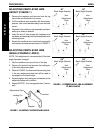
Hex Screws
Coved
Washers
Crossmember
Crossmember
Wheelchair
Frame
Front Mounting Hole
Rear
Mounting
Hole
FIGURE 4 - ADJUSTING SEAT WIDTH
SEAT PROCEDURE 6
S
E
A
T
ADJUSTING FRONT
SEAT-TO-FLOOR HEIGHT
WARNING
The position of the footrest, seat angle, back
angle, seating system/upholstery, caster size and
position, rear wheel size and position, anti-tippers,
as well as the user condition directly relate to the
stability of the wheelchair. Any change to one
(1) or any combination of the ten (10) may cause
the wheelchair to decrease in stability. EXTREME
care MUST be taken when changing the stability
of the wheelchair. Refer tothe chart in
STABILITY in
PROCEDURE 1 of this manual.
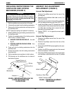
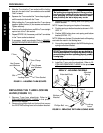
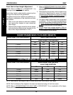
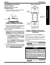
Determining Frame Height (FIGURE 5)
Terminator Jr. Frames come in Short and Tall.
1. To determine frame height, measure from the bot-
tom of the caster headtube to the top of the seat rail.
2. Refer to the chart to determine the frame size.
HEIGHT (INCHES) FRAME SIZE
7-3/4 SHORT
10-1/2 TALL
Seat Rail
Bottom of
Caster
Headtube
HEIGHT
(INCHES)
FIGURE 5 - DETERMINING FRAME HEIGHT