


29
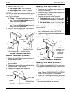
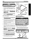
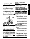
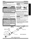
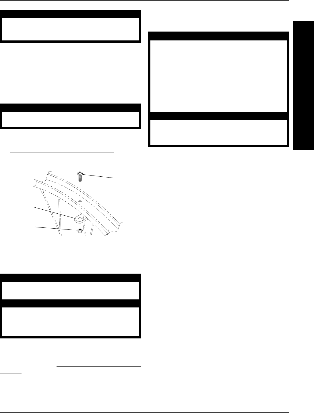
Allen
Screw
Locknut
Handrim
FIGURE 5 - HANDRIM REPLACEMENT
W
H
E
E
L
S
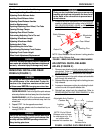
WHEELS PROCEDURE 7
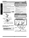
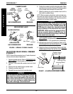
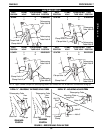
OPENING/CLOSING CLAMPS
(FIGURE 6)
WARNING
QUICK RELEASE LEVERS - Make sure the quick re-
lease levers are in the CLOSED position BEFORE
using the wheelchair, otherwise personal injury or
damage to the wheelchair may result.
STANDARD CAMBER OR RECEIVER TUBE CLAMPS
- Make sure the hex screws and locknuts are se-
curely tightened BEFORE using the wheelchair,
otherwise personal injury or damage to the
wheelchair may result.
CAUTION
DO NOT close the quick-release levers or tighten the
hex screws and locknuts without camber inserts in
the axle tube. Damage to the axle tube will occur.
Camber Clamps
1. Perform one (1) of the following to open a camber clamp:
A. QUICK RELEASE LEVERS - Pull the quick re-
lease lever to the open position.
B. STANDARD CAMBER CLAMPS - Loosen, but
do not remove the hex screw and locknut on the
camber clamp.
2. Perform one (1) of the following to close a camber clamp:
A. QUICK RELEASE LEVERS - Push the quick
release lever on the camber clamps to the closed
position.
B. STANDARD CAMBER CLAMPS - Securely tighten
the hex screw and locknut to secure the axle tube.
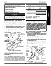
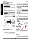
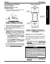
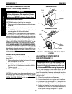
Receiver Tube Clamps
NOTE: The receiver tube clamps are used ONLY to
adjust wheelbase length.
1. Perform one (1) of the following to open a receiver
tube clamp:
A. QUICK RELEASE LEVERS - Pull the quick re-
lease levers on the receiver tube clamps to the
open position.
B. STANDARD RECEIVER TUBE CLAMPS -
Loosen, but do not remove the hex screws and
locknuts on the receiver tube clamps.
2. Perfrom one (1) of the following to close a receiver
tube clamp:
A. QUICK RELEASE LEVERS - Push the quick
release lever on the receiver tube clamps to the
closed position.
B. STANDARD RECEIVER TUBE CLAMPS -
Tighten the hex screw and locknut on the receiver
tube clamp.
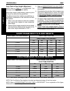
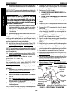
REPAIRING/REPLACING REAR
WHEEL, TIRE/TUBE
WARNING
Replacement of the tire or tube MUST be per-
formed by a qualified technician.
CAUTION
Changing the size of the rear wheels can affect
the performance of the wheelchair. Contact In-
vacare at the numbers on the back cover BE-
FORE performing this procedure.
NOTE: If replacing rear wheels with a different size than
what was originally on the wheelchair, the front caster height
must also be changed to keep the wheelchair frame parallel
to the floor. Refer to
ADJUSTING FRONT CASTER
HEIGHT in this procedure of the manual ONLY after con-
tacting Invacare. Anti-tipper height (if applicable) must also
be adjusted to maintain 1-1/2 to 2-inch clearance between
bottom of the anti-tipper wheels and the floor. Refer to
ANTI-
TIPPER REPLACEMENT/ADJUSTMENT in PROCE-
DURE 8 of this manual.
WARNING
Tire MUST be FULLY deflated BEFORE any disas-
sembly procedures are performed. Otherwise
injury or damage may result.
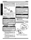
2. Remove all air from the tube by pressing down on the
pin in the center of the valve stem.
3. While carefully holding the tire, tube and rim strip to
one side, hold the allen screws and remove the lock-
nuts that secure the handrim to the rear wheel.
4. Remove the EXISTING handrim.
5. Install NEW handrim by reversing STEPS 2-4.
WARNING
DO NOT inflate tire until it is completely assembled.
Otherwise injury or damage may result.
6. Inflate tire to correct psi rating on the sidewall of tire.
7. Reinstall rear wheel to the wheelchair. Refer to
RE-
MOVING/INSTALLING REAR WHEELS in this pro-
cedure of the manual.
8. Repeat STEPS 1-7 for opposite rear wheel if necessary.