


18
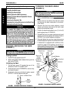
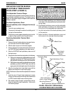
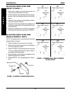
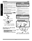
ADJUSTING CANTILEVER ARM
HEIGHT (FIGURE 1)
1. Remove the washers and locknuts from the top
hex screw and the bottom hex screw.
2. Pull the cantilever arm assembly with hex screws,
spacers, and coved washers away from the back
canes.
3. Reposition the cantilever arm assembly and hard-
ware up or down as desired.
4. Insert the two (2) hex screws with hardware and
cantilever arm assembly into the desired back cane
mounting holes.
5. Secure the cantilever arm to the back canes with
the locknuts and washers as shown in FIGURE 1.
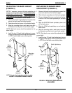
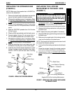
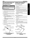
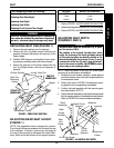
ADJUSTING CANTILEVER ARM
ANGLE (FIGURES 2 AND 3)
NOTE: This adjustment is recommended if the back
angle has been changed.
1. Flip the cantilever arm up and out of the way.
2. Remove the locknut that secures the locking pin
to the arm adjustment plate.
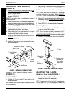
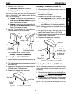
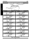
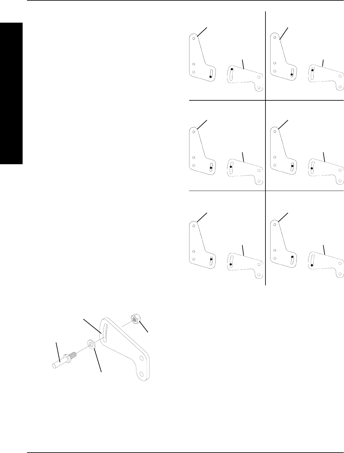
3. Refer to FIGURE 3 to determine the mounting hole
in the arm adjustment plate that will be used to
correspond to the back angle.
4. Securely tighten the locking pin and washer to the
adjustment plate with a locknut.
5. Repeat STEPS 1-4 for the opposite side, if neces-
sary.
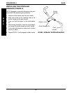
Adjustment Plate
Washer
Locknut
Locking Pin
FIGURE 2 - ADJUSTING CANTILEVER ARM ANGLE
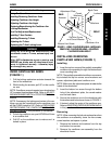
Back Angle Bracket
Arm
Adjustment
Plate
Back Angle Bracket
Arm
Adjustment
Plate
90
O
86
O
Back Angle Bracket
Arm
Adjustment
Plate
Back Angle Bracket
Arm
Adjustment
Plate
94
O
98
O
Back Angle Bracket
Arm
Adjustment
Plate
Back Angle Bracket
Arm
Adjustment
Plate
102
O
106
O
FIGURE 3 - CORRESPONDING ARM ADJUSTMENT
TO BACK ANGLE
PROCEDURE 5 ARMS
A
R
M
S