


12
B
A
C
K
PROCEDURE 4 BACK
This Procedure includes the following:
Folding/Unfolding the Back
Changing the Back Angle
Adjusting the Back Height
Replacing Standard Back Upholstery
Replacing Custom Manual Adjustable Tension
Back Upholstery
Replacing the Spreader Bar
Replacing the Locking Mechanism in the Back Cane
Installing the Stroller Handles
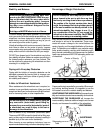
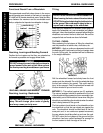
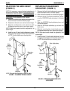
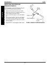
FOLDING/UNFOLDING THE BACK
(FIGURE 1)
WARNING
Back MUST be locked securely in place and all at-
taching hardware tight BEFORE using the wheelchair.
Folding the Back
1. Pull BOTH back release levers UP.
2. While holding BOTH back release levers, push the
back canes DOWN.
Unfolding the Back
1. Pull the back canes UP towards the rear of the
wheelchair there is an audible "click".
2. Push the back canes FORWARD to ensure they
are locked in place.
3. If the back canes are not locked in place, repeat
STEPS 1-2 until the back canes lock.
Back Cane
Back
Release
Lever
FIGURE 1 - FOLDING/UNFOLDING THE BACK
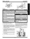
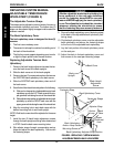
86°
90°
94°
98°
102°
106°
Locknut
Washer
Coved Washer
Front
Hex
Screw
Washer
Rear Hex
Screw
(Loosen,
but do not
Remove)
Back
Angle
Plate
Wheelchair
Frame
Seat Pan
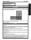
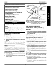
CHANGING THE BACK ANGLE
(FIGURE 2)
WARNING
The following procedure MUST be performed
by a qualified technician.
1. Remove the seat pan. Refer to
REPLACING SEAT
PAN in PROCEDURE 6 of this manual.
2. Loosen, but do not remove the rear hex screw
that secures the back angle plate to the wheel-
chair frame.
3. Remove the front hex screw, washers, coved
washer and locknut that secure the back angle
plate to the wheelchair frame.
4. Position the back angle plate to one (1) of six (6)
back angles shown in FIGURE 2.
5. Reinstall the front hex screw, washers and coved
washer and securely tighten with locknut. Refer to
FIGURE 2 for correct hardware orientation.
6. Securely tighten the rear hex screw that secures
the back adjustment plate to the wheelchair frame.
7. If wheelchair is equipped with cantilever arms,
adjust the angle of the cantilever arm so they re-
main parallel to the ground/floor. Refer to
ADJUST-
ING CANTILEVER ARM ANGLE in PROCEDURE
5 of this manual.
FIGURE 2 - CHANGING THE BACK ANGLE
BACK
ANGLES
WARNING
ALWAYS perform this procedure in the presence of
an assistant. The position of the footrest, camber
tube, back angle, the tautness of the back uphol-
stery as well as the user's condition are directly re-
lated to the wheelchairs stability. Any change to
one (1) or any combination of the five (5) may cause
the wheelchair to decrease in stability. Use EXTREME
caution when using a new seating position.
After ANY adjustments, repair or service and BEFORE
use, make sure all attaching hardware is tightened
securely - otherwise injury or damage may result.