


23
This Procedure includes the following:
Replacing Seat Pan
Adjusting Rear Seat Height
Adjusting Seat Depth
Adjusting Seat Width
Adjusting Front Seat-to-Floor Height
SEAT PROCEDURE 6
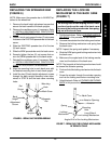
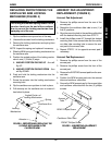
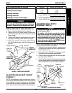
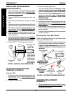
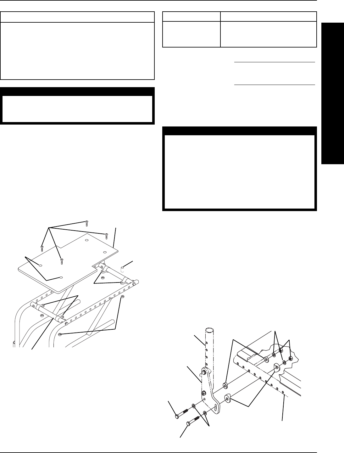
REPLACING SEAT PAN (FIGURE 1)
1. Remove the seat cushion from the seat pan.
2. Remove the four (4) phillips screws, locknuts and
spacers (if present) that secure the seat pan to the
frame clamps.
3. Position NEW seat pan on wheelchair frame, align-
ing seat pan mounting holes with frame clamps.
4. Secure the seat pan to the frame clamps with the
four (4) phillips screws, locknuts and spacers (if
present).
WARNING
After ANY adjustments, repair or service and BEFORE
use, make sure all attaching hardware is tightened
securely - otherwise injury or damage may result.
S
E
A
T
Phillips Screws
Locknuts
Wheelchair Frame
Frame
Clamps
Seat Pan
Seat Pan
Mounting
Holes
FIGURE1 - REPLACING SEAT PAN
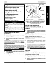
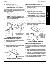
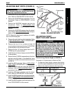
ADJUSTING REAR SEAT HEIGHT
(FIGURE 1)
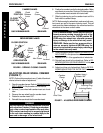
NOTE: The wheelchair frame is designed to create a
2-inch height difference between the front and the rear
of the seat pan. If desired, spacers can be added at
the rear of the seat pan to decrease this height differ-
ence. Refer to the chart below for the proper spacers.
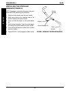
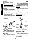
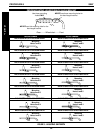
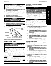
Rear
Hex
Screw
Front Hex Screw
Washers
Large
Coved
Spacers
Small Coved
Spacers
Locknuts
Wheelchair
Frame
Back
Angle
Bracket
Back
Assembly
FIGURE 2 - ADJUSTING SEAT DEPTH
FRONT OF
WHEELCHAIR
REAR OF
WHEELCHAIR
Spacer
SPACER HEIGHT DIFFERENCE
NONE 2-inch
1-inch 1-inch
2-inch NONE
1. Perform STEPS 1-2 of
REPLACING THE SEAT PAN.
2. Insert or remove spacers on top of the REAR frame clamps.
3. Perform STEPS 3-4 of
REPLACING THE SEAT PAN.
Washers
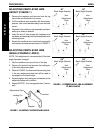
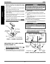
ADJUSTING SEAT DEPTH
(FIGURES 2 AND 3)
WARNING
This procedure must be performed by a quali-
fied technician ONLY.
The position of the footrest, camber tube, back
angle, the tautness of the back upholstery as well
as the user's condition are directly related to the
wheelchairs stability. Any change to one (1) or any
combination of the five (5) may cause the wheel-
chair to decrease in stability. Use EXTREME caution
when using a new seating position.
NOTE: Note the position of the front hex screw before
removing to ensure proper reinstallation.
1. Remove the hex screws, washers, coved spacers
and locknuts that secure the back angle brackets to
the wheelchair frame.
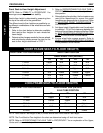
2. Refer to the chart in FIGURE 3 to determine mount-
ing positions for corresponding seat depths.
3. Position the back assembly with the mounting posi-
tion determined in STEP 2.
4. Secure the back assembly to the wheelchair frame with
the hex screws, washers, coved washers and locknuts.
Refer to FIGURE 2 for correct hardware orientation.