


17
PROCEDURE 5ARMS
A
R
M
S
This Procedure includes the following:
Using Cantilever Arms
Installing/Removing Cantilever Arms
Adjusting Cantilever Arm Height
Adjusting Cantilever Arm Angle
Replacing/Repositioning the Cantilever Arm
Locking Mechanism
Arm Pad Adjustment/Replacement
Installing T-Arm Sockets
Installing/Removing T-Arms
Adjusting the T-Arms
Replacing the T-Arm Locking Lever
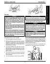
WARNING
Never try to lift or tip the wheelchair by the
cantilever arms or T-arms, serious injury can
occur.
After ANY adjustments, repair or service and
BEFORE use, make sure all attachment hard-
ware is tightened securely - otherwise, injury
or damage may occur.
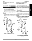
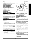
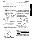
USING CANTILEVER ARMS
(FIGURE 1)
1. Pull the locking mechanism actuator towards the
front of the wheelchair.
2. While holding the actuator, pull UP on the cantile-
ver arm.
NOTE: If cantilever arms rub against rear wheels when
UP, increase the wheelbase width. Refer to ADJUST-
ING WHEELBASE WIDTH in PROCEDURE 7 of this
manual.
NOTE: If necessary, the locking mechanism in the can-
tilever arm can be repositioned so the cantilever arm
will flip DOWN instead of UP. Refer to
REPLACING/
REPOSITIONING THE CANTILEVER ARM LOCK-
ING MECHANISM in this procedure of the manual.
3. To lock the cantilever arm, push DOWN until there
is an audible click.
4. Pull UP on the cantilever arm to make sure it is
locked in place.
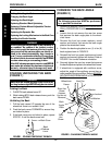
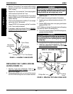
Washers
Locknuts
Back Cane
Actuator
Adjustment Plate
Cantilever Arm
Bottom Hex Screw
Top Hex Screw
and Coved Washer
Coved
Washers
Spacer
FIGURE 1 - USING CANTILEVER ARMS - INSTALLING/
REMOVING CANTILEVER ARMS - ADJUSTING
CANTILEVER ARM HEIGHT
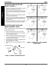
INSTALLING/REMOVING
CANTILEVER ARMS (FIGURE 1)
Installing
1. Insert the top hex screw of the partially assembled
cantilever arm assembly through the desired back
cane mounting hole.
NOTE: The partially assembled cantilever arm assem-
bly includes the top hex screw, coved washers and
spacer, adjustment plate and cantilever arm.
NOTE: Make sure the adjustment plate is towards the
inside of the wheelchair.
2. Insert the bottom hex screw through the bottom
hole of the adjustment plate, the coved washer
and the back cane.
3. Secure the cantilever arm to the wheelchair with
the washers and locknuts as shown in FIGURE 1.
4. If desired, adjust the angle of the cantilever arm.
Refer to
ADJUSTING CANTILEVER ARM ANGLE
in this procedure of the manual.
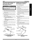
Removing
NOTE: When removing the locknuts and washers from
the cantilever arm assembly, leave the hex screws,
coved washers and spacer in place.
1. Remove the locknuts and washers from the top
and bottom hex screws.
2. Remove the cantilever arm assembly from the
wheelchair frame.
REAR
FRONT