


78
15. Repeat STEPS 2-14 for the opposite side of the wheel-
chair, if necessary.
16. Tighten the jamnut on the stabilizer cylinder.
WARNING
Stabilizers MUST be adjusted BEFORE use, oth-
erwise they will NOT operate properly.
17. Adjust the front stabilizer(s). Refer to
ADJUSTING
STABILIZERS in this procedure of the manual.
18. If necessary, install the front shroud. Refer to
REMOV-
ING/INSTALLING SHROUDS in PROCEDURE 10
of this manual.
2. Remove the battery boxes. Refer to INSTALLING/
REMOVING BATTERY BOXES in this procedure of
the manual.
3. Remove the tip from the existing clutch handle.
4. Remove the pin that secures the existing clutch handle
to the motor/gearbox.
5. Disconnect the existing clutch handle from the motor/
gearbox.
6. Feed the existing clutch handle through the wheel-
chair frame.
7. Remove the rubber tip from the new clutch handle.
8. Install the new clutch handle onto the wheelchair.
NOTE: Make sure the new clutch handle is pointing to-
wards the outside of the wheelchair.
9. Install the rubber tip onto the new clutch handle.
10. Connect the clutch handle to the motor/gearbox and
line up the mounting holes in the clutch handle and
motor/gearbox.
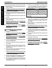
11. Insert the pin through the clutch handle and motor/
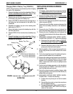
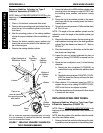
gearbox as shown in DETAIL "A" in FIGURE 21.
NOTE: Make sure the detent ball on the pin is fully visible.
12. Repeat STEPS 3-11 for the opposite side of the wheel-
chair, if necessary.
13. Reinstall the battery boxes. Refer to
INSTALLING/
REMOVING BATTERY BOXES in this procedure of
the manual.
14. If necessary, install the shrouds. Refer to
REMOV-
ING/INSTALLING SHROUDS in PROCEDURE 10
of this manual.
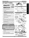
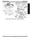
FIGURE 21 - REPLACING CLUTCH HANDLES -
RANGER II MWD BASIC
Tip
(STEPS 3, 7, 9)
Outside of
Wheelchair
Motor/
Gearbox
Clutch Handle
(STEPS 5, 8)
Clutch Handle
(STEP 10)
Pin
(STEPS 4, 11)
Detent Ball
Motor/Gearbox
DETAIL "A"
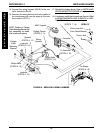
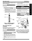
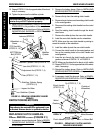
Stabilizer
Cylinder
Wheelchair
Frame
Locknuts
(STEPS 3,
13)
TOP Hex Bolt
(STEPS 3, 13)
BOTTOM Hex
Bolt
(STEPS
4, 14)
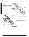
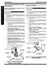
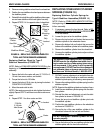
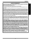
FIGURE 16 - REPLACING STABILIZER CYLINDER
SPRINGS
Stabilizer Cylinder
Stabilizer Cylinder Spring
(STEPS 8, 9)
Adjustment Nut
(STEPS 7, 9)
Plate
(STEPS 7, 10)
Stabilizer Cylinder Pivot
(STEPS 6, 11)
Jam Nut
(STEPS 2, 11, 16)
Inspect for Wear
Stabilizer Plates
MWD WHEELCHAIRS
M
W
D
W
H
E
E
L
C
H
A
I
R
S
PROCEDURE 14
REPOSITIONING MOTORS
WARNING
Repositioning the motors MUST be performed by an
authorized Invacare dealer or qualified technician.
REPLACING CLUTCH HANDLES -
R2
BASIC
AND R2
250 SERIES
(FIGURE 21)
1. If necessary, remove the shrouds. Refer to REMOV-
ING/INSTALLING SHROUDS in PROCEDURE 10
of this manual.