


24
ELECTRONICS
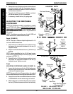
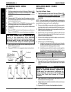
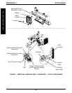
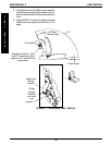
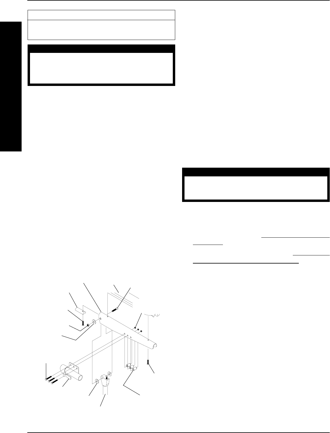
FIGURE 1 - REPOSITIONING MKIV JOYSTICK
- CAPTAIN’S SEATS
Adjustment Lock
Hex Bolts
(STEPS 3, 16)
Spacers
(STEPS 3, 17)
Locknuts
(STEPS 3, 17)
Phillips Screw
(STEPS 4, 14)
Armrest Insert
Phillips Screw
(STEPS 5, 13)
Armrest Pad
Armrest Plate
Lug Bolt
(STEPS 7, 9)
Washers
(STEPS 7, 9)
Locknuts
(STEPS 7, 9)
Seat Frame Assembly
This Procedure Includes the Following:
Repositioning MKIV Joystick
Removing/Installing MKIV Controller
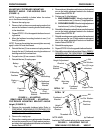
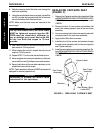
REPOSITIONING MKIV JOYSTICK
Captain’s Seats (FIGURE 1)
1. Turn the lever on the adjustment lock to release the
adjustment lock from joystick mounting tube.
2. Remove the joystick from the wheelchair.
3. Remove the three (3) hex bolts, spacers and locknuts
that secure joystick mounting bracket to armrest plate.
4. Remove the phillips screw that secures the front of the
armrest pad to the armrest plate.
5. Remove the phillips screw that secures the rear of the
armrest pad and armrest insert to the armrest plate.
6. Remove the armrest pad from the armrest plate.
7. Remove the lug bolt, washers and locknut that secure
the existing armrest plate to the seat frame assembly.
8. Repeat STEPS 4-7 for opposite side of wheelchair.
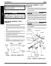
9. Position armrest plate with joystick mounting holes on
desired side of seat frame assembly and secure with
lug bolt, washers and locknut. Refer to FIGURE 1.
10. Position armrest plate without joystick mounting holes
on opposite side of seat frame assembly and secure
with lug bolt, washers and locknut. Refer to FIGURE 1.
WARNING
After ANY adjustments, repair or service
and BEFORE use, make sure all attaching
hardware is tightened securely - other-
wise injury or damage may result.
Washers
(STEPS 7, 9)
E
L
E
C
T
R
O
N
I
C
S
PROCEDURE 7
11. Position the armrest pad on the armrest plate.
12. Line up the mounting holes in the armrest insert, arm-
rest plate and armrest pad.
13. Reinstall rear phillips screw through the armrest insert,
armrest plate and armrest pad and tighten securely.
14. Reinstall the front phillips screw into the armrest plate
and armrest pad and tighten securely.
15. Repeat STEPS 11-14 for opposite side of wheelchair.
16. Install Loctite 242 onto the three (3) hex bolts.
17. Install the three (3) hex bolts, spacers and locknuts that
secure joystick mounting bracket to armrest plate.
18. Slide the joystick mounting tube through the joystick
mounting bracket to the desired position.
19. Secure adjustment lock to joystick mounting tube by
turning lever on adjustment lock.
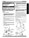
REMOVING/INSTALLING MKIV
CONTROLLER
WARNING
Replacement controller MUST be same part
number as factory installed controller -
Otherwise, injury or damage may result.
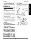
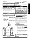
16, 18, or 20-inch Wide Models (FIGURE 2)
REMOVING.
1. If necessary, remove the rear shroud and rear compart-
ment (if equipped). Refer to
REMOVING/INSTALLING
SHROUDS in PROCEDURE 10 of this manual.
2. Remove the battery boxes. Refer to
REMOVING/
INSTALLING THE BATTERY BOXES for one (1)
of the following:
FWD WHEELCHAIRS - in PROCEDURE 13
of this manual.
MWD WHEELCHAIRS - in PROCEDURE 14
of this manual.
3. Disconnect the following connections:
A. The right hand motor and controller connection.
B. The left hand motor and controller connection.
C. Battery wiring harness and controller connection.
4. Remove the two (2) locknuts that secure the existing
MKIV controller and washer(s) to the wheelchair.
5. Remove existing MKIV controller from the wheelchair.
INSTALLING.
1. Install washer(s) onto rear mounting stud.
2. Install new/existing MKIV controller onto wheelchair
frame.