


57
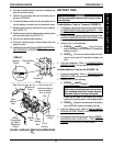
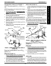
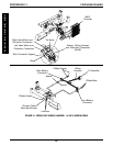
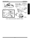
14-inch Wide Models (FIGURE 19)
1. Remove the shrouds. Refer to
REMOVING/INSTALL-
ING SHROUDS in PROCEDURE 10 of this manual.
2. Remove the battery boxes. Refer to
REMOVING/IN-
STALLING THE BATTERY BOXES in PROCEDURE
12 of this manual.
3. Cut the tie wrap that secure the following connections
to the wire connector support:
A. The right hand motor and controller connection.
B. The left hand motor and controller connection.
C. Battery wiring harness and controller connection.
(BLUE)
4. Disconnect the battery wiring harness (BLUE) and
controller connector (BLUE).
5. Remove the two (2) phillips screws and spacers that
secure the rear battery connector to the wheelchair
frame.
6. Remove the two (2) phillips bolts and locknuts that
secure the front battery connector to wheelchair frame.
7. Remove the two (2) phillips screws that secure the
wiring harness to the charger cable mounting bracket.
8. Remove the existing wiring harness from wheelchair.
9. Position the rear battery connector of the new wiring
harness on the wheelchair frame as shown in FIG-
URE 19 and secure with the two (2) phillips screws
and spacers.
10. Position the front battery connector on the wheelchair
frame as shown in FIGURE 19 and secure with the
two (2) phillips bolts and locknuts.
11. Secure the wiring harness to existing charger cable
mounting bracket on the seat frame with the two (2)
phillips screws.
12. Connect the wiring harness (BLUE) to the controller
connector (BLUE).
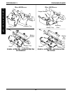
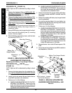
NOTE: See FIGURE 19 for proper positioning of con-
nections on wire connector support.
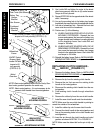
13. Postion the right hand motor/controller connection and
the left hand motor/controller connection side by side
on the wire connector support.
14. Postion the battery wiring harness/controller con-
nection on top of the right/left hand motor/con-
troller connections.
NOTE: When securing the above connections to wire
connector support, make sure to wrap tie-wrap around
crossbrace and thread through slot in wire connector
support.
15. Secure the connections stated in STEPS 13 and 14
to the wire connector support with a tie-wrap.
16. Install the battery boxes. Refer to
REMOVING/
INSTALLING THE BATTERY BOXES in PRO-
CEDURE 12 of this manual.
17. Install the shrouds. Refer to
REMOVING/INSTALL-
ING SHROUDS in PROCEDURE 10 of this manual.
F
W
D
W
H
E
E
L
C
H
A
I
R
S
PROCEDURE 13FWD WHEELCHAIRS