


25
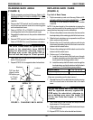
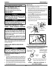
MKIV
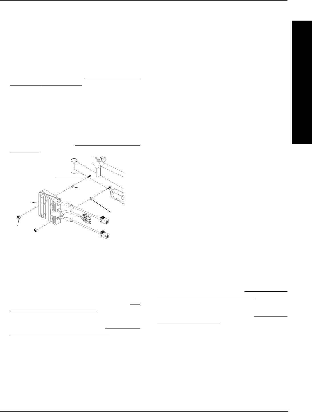
Controller
Locknuts
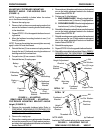
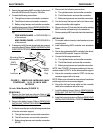
FIGURE 2 - REMOVING/INSTALLING MKIV
CONTROLLER - 16,18, 20-INCH WIDE
MODELS
Mounting Stud on
Wheelchair Frame
Washer
Washer -
MWD
Only
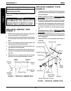
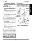
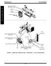
14-inch Wide Models (FIGURE 3)
REMOVING.
1. Remove the front and rear shrouds. Refer to
RE-
MOVING/INSTALLING SHROUDS in PROCEDURE
10 of this manual.
2. Remove the battery boxes. Refer to
REMOVING/
INSTALLING THE BATTERY BOXES in PROCE-
DURE 12 of this manual.
3. Cut the tie wrap that secure the following connections
to the wire connector support:
A. The right hand motor and controller connection.
B. The left hand motor and controller connection.
C. Battery wiring harness and controller connection.
(BLUE)
3. Secure the new/existing MKIV controller to the wheel-
chair with NEW locknuts. Torque to 156-in/lbs.
4. Connect the following connections:
A. The right hand motor and controller connection.
B. The left hand motor and controller connection.
C. Battery wiring harness and controller connection.
5. Install the battery boxes. Refer to
REMOVING/INSTALL-
ING THE BATTERY BOXES for one (1) of the follow-
ing:
FWD WHEELCHAIRS - in PROCEDURE 13
of this manual.
MWD WHEELCHAIRS - in PROCEDURE 14
of this manual.
6. If necessary, install the rear shroud and rear compart-
ment (if equipped). Refer to
REMOVING/INSTALLING
SHROUDS in PROCEDURE 10 of this manual.
4. Disconnect the following connections:
A. The right hand motor and controller connection.
B. The left hand motor and controller connection.
C. Battery wiring harness and controller connection.
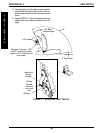
5. Cut the tie-wrap that secure the the left hand motor
cable and controller cable together.
6. Remove the two (2) locknuts that secure the existing
MKIV controller and washer(s) to the wheelchair.
7. Remove existing MKIV controller from the wheelchair.
INSTALLING.
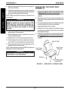
1. On models without shrouds, install washer onto rear
mounting stud.
2. Install new/existing MKIV controller onto wheelchair
frame.
3. Secure the new/existing MKIV controller to the wheel-
chair with NEW locknuts. Torque to 156-in/lbs.
4. Connect the following connections:
A. The right hand motor and controller connection.
B. The left hand motor and controller connection.
C. Battery wiring harness and controller connection.
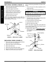
NOTE: See FIGURE 3 for proper positioning of the con-
nections noted in STEP 4 on the wire connector support.
5. Secure the connections noted in STEP 4 to the wire
connector support with a tie-wrap
NOTE: Make sure to thread tie-wrap around crossbrace
and through slot in wire connector support.
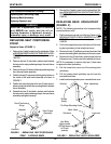
6. Secure the left hand motor cable and the controller
cable to the crossbrace with a tie-wrap .
7. Install the battery boxes. Refer to
REMOVING/IN-
STALLING THE BATTERY BOXES in PROCE-
DURE 12 of this manual.
8. Install the front and rear shroud. Refer to
REMOVING/
INSTALLING SHROUDS in PROCEDURE 10 of this
manual.
E
L
E
C
T
R
O
N
I
C
S
PROCEDURE 7ELECTRONICS