


71
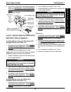
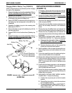
Changing Width of Battery Tray (FIGURE 9)
NOTE: This procedure is only necessary when changing
the width of the wheelchair.
1. Remove the battery tray from the wheelchair. Refer to
INSTALLING/REMOVING BATTERY TRAY in this
procedure of the manual.
2. Remove the hex bolt and locknut that secure one (1)
of the battery tray pins to the battery tray.
3. Refer to FIGURE 9 to determine the mounting hole in
the battery tray that corresponds to the width of the
wheelchair.
4. Reposition the battery tray pin to the mounting hole
determined in STEP 3.
5. Secure the battery tray pin to the battery tray with the
hex bolt and locknut.
6. Repeat STEPS 2-5 for the other three (3) battery tray
pins.
7. Reinstall the battery tray onto the wheelchair. Refer to
INSTALLING/REMOVING BATTERY TRAY in this
procedure of the manual.
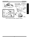
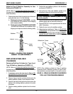
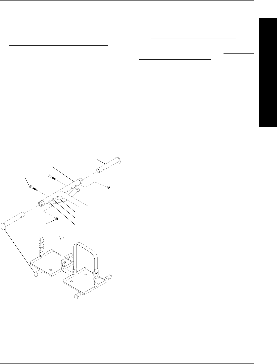
FIGURE 9 - BATTERY TRAY - CHANGING WIDTH OF
BATTERY TRAY
18-inch Wheelchair
20-inch Wheelchair
Battery Tray Pins
Battery Tray
Hex Bolts
Locknuts
16-inch Wheelchair
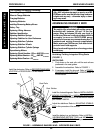
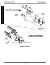
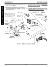
REPLACING WIRING HARNESS
(FIGURE 10)
1. If necessary, remove the front and rear shrouds. Re-
fer to
REMOVING/INSTALLING SHROUDS in PRO-
CEDURE 10 of this manual.
2. Remove the battery boxes. Refer to
INSTALLING/
REMOVING BATTERY BOXES in this procedure of
manual.
3. Disconnect the wiring harness (BLUE) from the con-
troller connector (BLUE).
4. Remove the two (2) phillips screws and spacers that
secure the rear battery connector to the wheelchair
frame.
5. Remove the two (2) phillips bolts and locknuts that
secure the front battery connector to wheelchair frame.
6. Remove the two (2) phillips bolts and locknuts that
secure the wiring harness to the charger cable mount-
ing bracket.
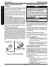
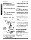
7. HIGH BACK CAPTAIN'S SEAT MODEL WHEEL-
CHAIRS ONLY (DETAIL "A") - Perform the following:
A. Disconnect the limit switch. Refer to
DISCON-
NECTING/CONNECTING LIMIT SWITCH in this
procedure of the manual.
B. Remove the phono jack nut that secures the
phono jack to the limit switch bracket.
8. Note the position of the tie wraps that secure the ex-
isting wiring harness and motor cables to the cross-
braces.
9. Cut the tie wraps that secure the existing wiring har-
ness and motor cables to the crossbraces.
10. Remove the existing wiring harness from wheelchair.
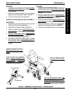
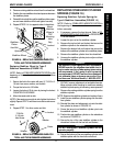
11. Position the rear battery connector of the new wiring
harness on the wheelchair frame as shown in FIG-
URE 10 and secure with the two (2) phillips screws
and spacers.
12. Position the front battery connector on the wheelchair
frame as shown in FIGURE 10 and secure with the
two (2) phillips bolts and locknuts.
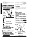
13. Secure the wiring harness to existing charger cable
mounting bracket on the seat frame with the two (2)
phillips bolts and locknuts.
14. HIGH BACK CAPTAIN'S SEAT MODEL WHEEL-
CHAIRS ONLY - Perform the following:
A. Position the new phono jack on the limit switch
bracket.
B. Reinstall the phono jack nut onto the new phono
jack and tighten securely.
C. Connect the limit switch. Refer to DISCONNECT-
ING/CONNECTING LIMIT SWITCH in this pro-
cedure of the manual.
PROCEDURE 14MWD WHEELCHAIRS
M
W
D
W
H
E
E
L
C
H
A
I
R
S