


17
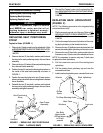
4. Remove the nut, flat washer and that secure the threaded
arm on the height adjustment bracket to the footboard
bracket. Refer to DETAIL “B”.
5. Perform one (1) of the following:
A. MWD WHEELCHAIRS - Move the height adjust-
ment bracket to one (1) of seven (7) height positions.
B. FWD WHEELCHAIRS - Move the height adjustment
bracket to one (1) of five (5) height positions.
6. Reinstall the flat washer and nut that secures the threaded
arm on the height adjustment bracket to the footboard
bracket. Refer to DETAIL “B”.
7. Reinstall mounting screw, caplug washer, flat washer and
nut that secures the two (2) large washers and support
tube to the height adjustment bracket and footboard
bracket. Refer to DETAIL “A”.
8. Reinstall the caplug caps.
9. Repeat STEPS 2-8 for the opposite footboard bracket.
10. Reinstall the removable footboard plate. Refer to
REMOV-
ING/INSTALLING THE REMOVABLE FOOTBOARD
ONTO/FROM THE WHEELCHAIR in PROCEDURE
3 of the Owner’s Manual.
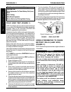
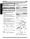
ADJUSTING FOOTBOARD MOUNTING
BRACKET ANGLE - FWD MODELS ONLY
(FIGURE 4).
NOTE: Angle availability is limited when the motors
are in the forward-most position.
1. Remove the caplug cap.
2. Remove the front hex screw and caplug washer that
secure the footboard mounting bracket and bushing
to the wheelchair.
3. Repeat STEPS 1-2 for the opposite footboard mount-
ing bracket.
4. Move the footboard mounting brackets to one (1) of
three (3) positions.
NOTE: To ensure the existing hex screws tighten securely,
apply Loctite 242 onto the threads.
5. Reinstall the two (2) hex screws and caplug washers
through the two (2) footboard mounting brackets and
bushings and into the wheelchair.
6. Torque the two (2) hex screws to 13-ft/lbs.
7. Reinstall the two (2) caplug caps.
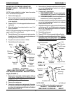
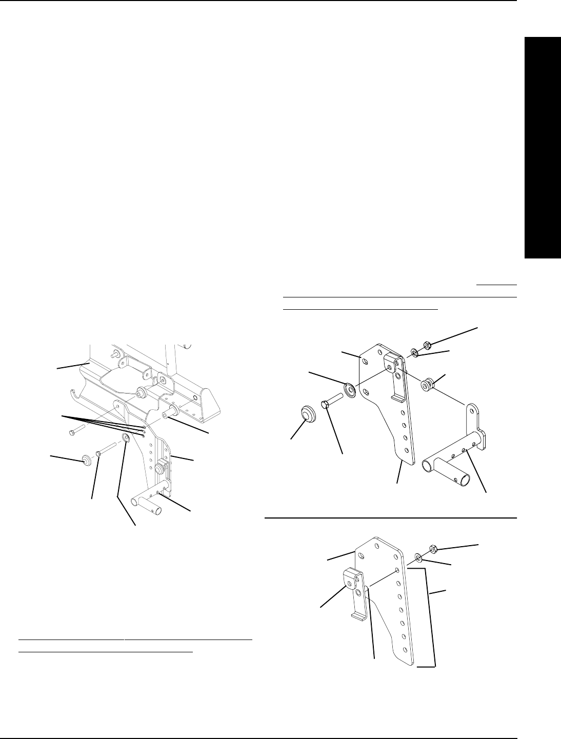
Height (FIGURE 5)
1. Remove the removable footboard plate. Refer to
PREPARING REMOVABLE FOOTBOARD FOR
WHEELCHAIR TRANSPORTATION in PROCE-
DURE 3 of the Owner’s Manual.
2. Remove the caplug cap.
3. Remove the mounting screw, caplug washer, flat washer
and nut that secures the two (2) large washers and sup-
port tube to the height adjustment bracket and footboard
bracket. Refer to DETAIL “A”.
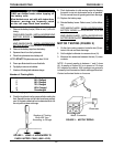
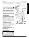
FIGURE 4 - ADJUSTING
REMOVABLE FOOTBOARD - ADJUSTING
FOOTBOARD MOUNTING BRACKET ANGLE
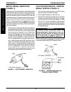
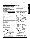
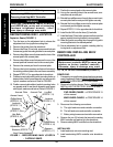
FIGURE 5 - ADJUSTING FLIP-UP
REMOVABLE FOOTBOARD - HEIGHT
Bushing
Footboard
Pivot
Assemblies
Front Hex
Screw
Caplug
Cap
Caplug
Washer
Battery
Tray
3 Mounting
Positions
Footboard
Mounting
Bracket
PROCEDURE 3
F
R
O
N
T
R
I
G
G
I
N
G
S
FRONT RIGGINGS
NOTE: MWD footboard bracket shown for clarity. Footboard
bracket on FWD models adjusts in the same manner.
Footboard
Bracket
Nut
Flat Washer
Mounting
Positions
Threaded Arm
Height
Adjustment
Bracket
DETAIL “B”
Caplug
Cap
Mounting
Screw
Caplug
Washer
Flat Washer
Nut
Height Adjustment
Bracket
Footboard
Bracket
Two (2) Large
Washers
Support Tube
DETAIL “A”