SECTION 4—FRONT RIGGINGS
Tracer® EX2 22 Part No. 1110546
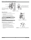
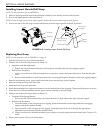
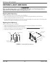
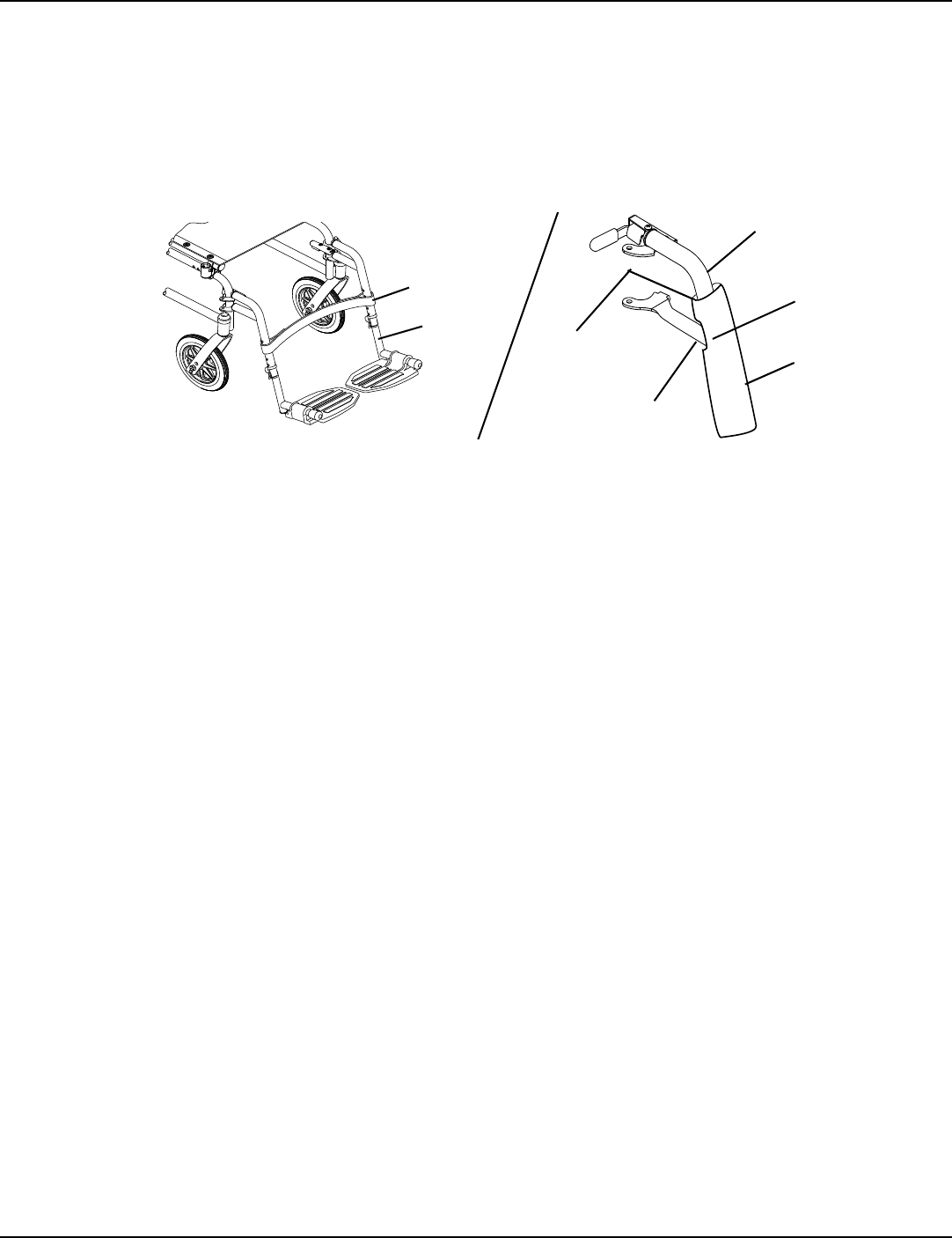
Installing Impact Guards/Calf Strap
NOTE:Forthisprocedure,refertoFIGURE 4.6.
1. Removeimpactguard/calfstrapfrompackagedcontainerifnotalreadysecuredtothefootrest.
2. Secureoneimpactguardtotheeachfootrest.
NOTE:Ensuretheupperportionoftheimpactguardisbetweenthetwohorizontalsupportsofthefootrest.
3. Secureonesideofthecalf
straparoundeachfootrest(withtheimpactguardsattached,ifpresent).
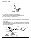
FIGURE 4.6 Installing Impact Guards/Calf Strap
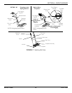
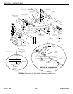
Replacing Heel Loop
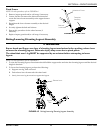
NOTE:Forthisprocedure,refertoFIGURE 4.7onpage23.
1. Pullthecamlockleveruptounlockedposition.
2. PerformoneofthefollowingasshowninDetailʺAʺ.
• FootplateswithSpringButtons:
i. Pushinthereleasebuttonsandremovethefootplateassemblyfromthefrontriggingsupport.
•Bolt‐In‐PlaceFootplates:
i. Usingascrewdrivertoholdthethreadedrivetinposition,removethebuttonheadscrewfromthethreaded
rivet.
ii. Removethethreadedrivetandbuttonheadscrewsecuringthefootplateassemblytothefrontriggingsupport.
3. Removethemountingscrew,spacerandlocknutthatsecuretheheellooptothefootplate.
4. Removeexistingheelloopfromslidetube.
5. Installnewheelloopontoslidetube.
6. Installthemountingscrew,spacerandlocknuttosecuretheheellooptothefootplate.Tightenuntilthespacerissecure.
7. Insertthelowerfootrestassemblyintotheupperfootrestassemblytodesiredheight.
8. Performoneofthefollowing
asshowninDetailʺAʺ:
• FootplatesWithSpringButtons:
i. Ensurethatthereleasebuttonsfullyprotrudefromholesonbothsidesoftheupperfootrestsupport.
•Bolt‐In‐PlaceFootplates:
i. Fromtheoutsideoftheswingawayfrontrigging,insertthethreadedrivetthroughboththefrontrigging
supportandthefootplate
assembly.
ii. Fromtheinsideoftheswingawayfrontrigging,insertthebuttonheadscrewthroughtheappropriate
adjustmentholeandthreadintothethreadedrivet.
iii. Usingascrewdrivertoholdthethreadedrivetinposition,securelytightenthebuttonheadscrew.Torqueto32
in‐lbs.
9. Rotatecamlockleverdownto
lockedposition.
Calf Strap
Footrest
Horizontal Support
Upper Portion of
Impact Guard
Impact
Guard
Notch
Horizontal
Support


