


SECTION 4—FRONT RIGGINGS
Tracer® EX2 20 Part No. 1110546
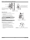
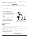
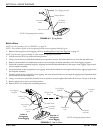
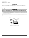
FIGURE 4.2 Spring Button
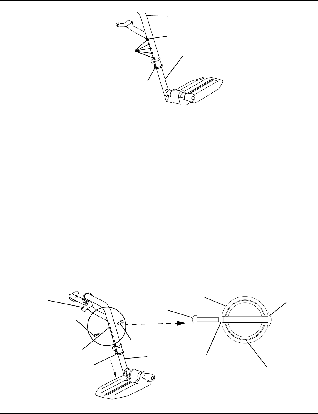
Bolt-In-Place
NOTE:Forthisprocedure,refertoFIGURE 4.3onpage20.
NOTE:Thisprocedureappliestotheswingawayfootrestsandswingawayelevatinglegrest.
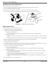
1. Removetheswingawayfrontrigging.RefertoInstalling/RemovingFrontRiggings
onpage 19.
NOTE:Laythefrontriggingassemblyonaflatsurfacetosimplifythisprocedure.
2. Pullthecamlockleveruptotheunlockedposition.
3. Usingascrewdrivertoholdthethreadedrivetinposition,removethebuttonheadscrewfromthethreadedrivet.
4. Removethethreadedrivetandbutton
headscrewsecuringthefootplateassemblytothefrontriggingsupport.
5. Adjustthefootplateassemblyheightbyaligningthedesiredadjustmentholesintheupperfrontriggingsupportand
lowerfootplateassembly.
6. Fromtheoutsideoftheswingawayfrontrigging,insertthethreadedriv etthroughboththefrontriggingsupportand
the
footplateassembly.
7. Fromtheinsideoftheswingawayfrontrigging,insertthebuttonheadscrewthroughtheappropriateadjustmenthole
andthreadintothethreadedrivet.
8. Usingascrewdrivertoholdthethreadedrivetinposition,securelytightenthebuttonheadscrew.Torqueto32in‐lbs.
9. Rotatecamlockleverdown
tolockedposition.
10. RepeatSTEPS1‐9toadjusttheremainingfootrest.
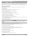
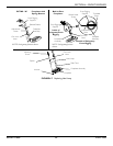
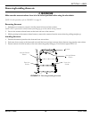
FIGURE 4.3 Bolt-In-Place
Front Rigging Support
Release Button
Footplate
Assembly
Cam Lock Lever
Adjustment
Holes
NOTE:Swingawayfootrestshown.
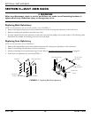
Front Rigging
Support
Button Head
Screw
Threaded Rivet
Footplate
Assembly
NOTE:Swingawayfootrestshown.
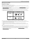
Footplate
Assembly
Threaded
Rivet
Front Rigging
Support
Button Head
Screw
Adjustment
Hole
Inside of
Swingaway
Front Rigging
Adjustment
Hole
Cam Lock
Lever
Outside of
Swingaway
Front Rigging