


7
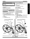
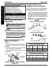
Caster Size Seat-to-floor Caster Mounting Position Rear Wheel Size Rear Wheel Position
6 15.5 Top 20 *Top
6 16.5 Middle 22 *Top
6 17.5 Bottom 24 *Top
6 17.5 Bottom 20 Bottom
8 17.5 Top 20 Bottom
8 17.5 Top 24 *Top
8 18.5 Middle 22 Bottom
8 19.5 Bottom 24 Bottom
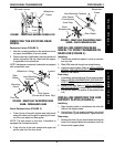
PROCEDURE 2
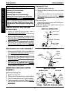
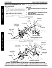
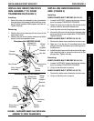
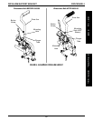
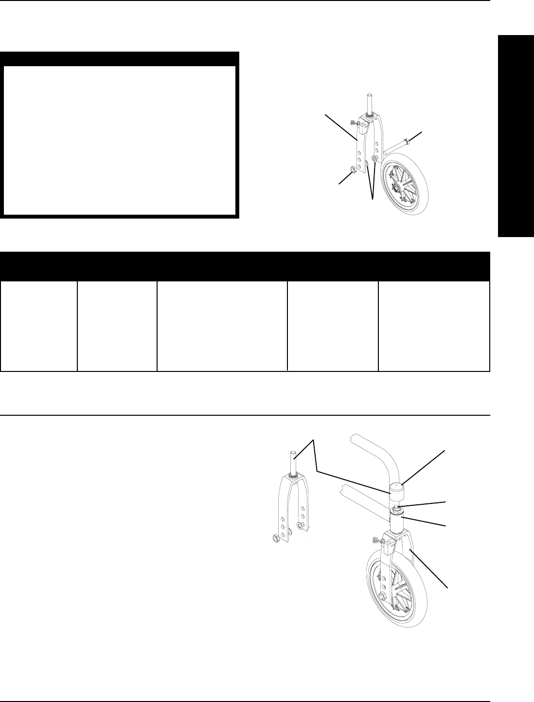
FIGURE 2 - MOUNTING CASTER TO CLD FORK
ASSEMBLY
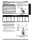
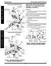
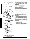
INSTALLING CLD FORK ASSEMBLY
ONTO WHEELCHAIR (FIGURE 3)
1. Remove the hex nut from the CLD fork stem.
2. Insert the CLD fork stem into the caster headtube.
3. Secure the CLD fork assembly to the caster headtube
with the hex nut.
NOTE: DO NOT overtighten the hex nut. The CLD fork
should turn freely with no side to side play.
4. Install the caster journal cap onto the caster headtube.
CLD Fork Stem
Caster
Journal
Cap
Hex Nut
Fork
F
O
R
K
A
S
S
E
M
B
L
Y
FORK ASSEMBLY
Hex
Screw
Hex Nut
Washers
CLD Fork
Assembly
Caster
Headtube
MOUNTING CASTER TO CLD FORK
ASSEMBLY (FIGURE 2)
WARNING
If not changing the wheelchair's current configu-
ration (seat angle, caster size or seat-to-floor
height), refer to the chart below to determine
the caster and/or rear wheel mounting positions.
If changing the wheelchair's current configuration
(seat angle, caster size or seat-to-floor height), re-
fer to the 9000 Wheelchair Service Manual, Part
Number 1076155.
When installing the CLD onto 9000 wheelchairs with
specific measurements, the wheelchairs MUST be
equipped with the space saver arms. Refer to the
chart below for specific measurements.
NOTE: Measurements in the chart are in inches.
1. Refer to the chart below to determine which mount-
ing position should be used.
2. Secure the caster to the CLD fork assembly in the
mounting position determined in STEP 1 with the hex
head bolt, washers and the hex nut as shown in FIG-
URE 2. Tighten securely.
9000 WHEELCHAIRS
FIGURE 3 - INSTALLING CLD FORK ASSEMBLY
ONTO WHEELCHAIR
*Space Saver Arms required for 9000 wheelchairs.