


22
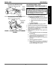
PROCEDURE 7 FRONT RIGGING
This procedure includes the following:
Installing CLD Front Rigging Release Handle
WARNING
After ANY adjustments, repair or service and BE-
FORE use, make sure all attaching hardware is
tightened securely - otherwise injury or damage
may result.
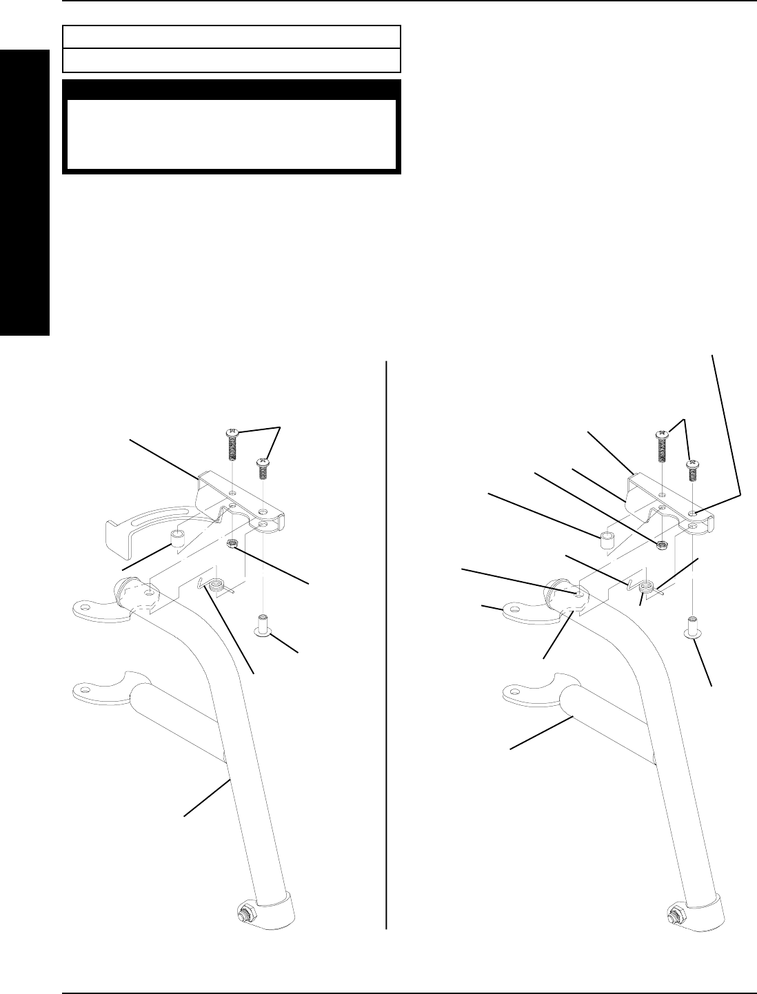
INSTALLING CLD FRONT RIGGING
RELEASE HANDLE (FIGURE 1)
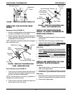
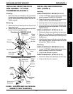
1. Remove the two (2) pan head screws, hex nut, riv
nut, bushing and spring from the EXISTING front
rigging release handle and retain for later use.
2. Position the bushing between the two (2) mounting
holes near the tab on the CLD release handle.
Riv Nut
Pan
Head
Screws
Bushing
Hex
Nut
Spring
Existing Release
Handle
Riv Nut
Pan
Head
Screws
Bushing
Hex Nut
Spring
CLD Release
Handle
Front Rigging
Front
Rigging
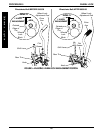
FIGURE 1 - INSTALLING CLD FRONT RIGGING RELEASE HANDLE
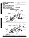
Tab
Mounting
Plate
3. Secure the bushing to the CLD release handle with
a pan head screw and hex nut. Tighten securely.
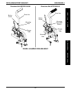
4. Position mounting hole "A" UNDER mounting hole
"B".
5. Position the hole in the spring UNDER mounting hole
"A" in the orientation shown in FIGURE 1.
NOTE: The bent portion of the spring should hook over
the mounting plate as indicated in FIGURE 1 and the
straight end of the spring should rest inside the CLD re-
lease handle and point away from the tab.
6. Secure the spring and CLD release handle to the
mounting plate with the remaining pan head screw
and riv nut. Tighten securely.
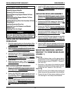
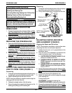
EXISTING
CLD
HOOK
SPRING HERE
F
R
O
N
T
R
I
G
G
I
N
G
Mounting
Hole "A"
Mounting Hole "B"
Bent Portion
of Spring
Straight
Portion
of Spring