


5
NOTE: The procedures in this manual should be per-
formed on the specific side of the wheelchair the CLD
was ordered for.
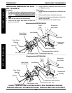
ASSEMBLIES (FIGURE 1)
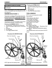
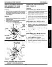
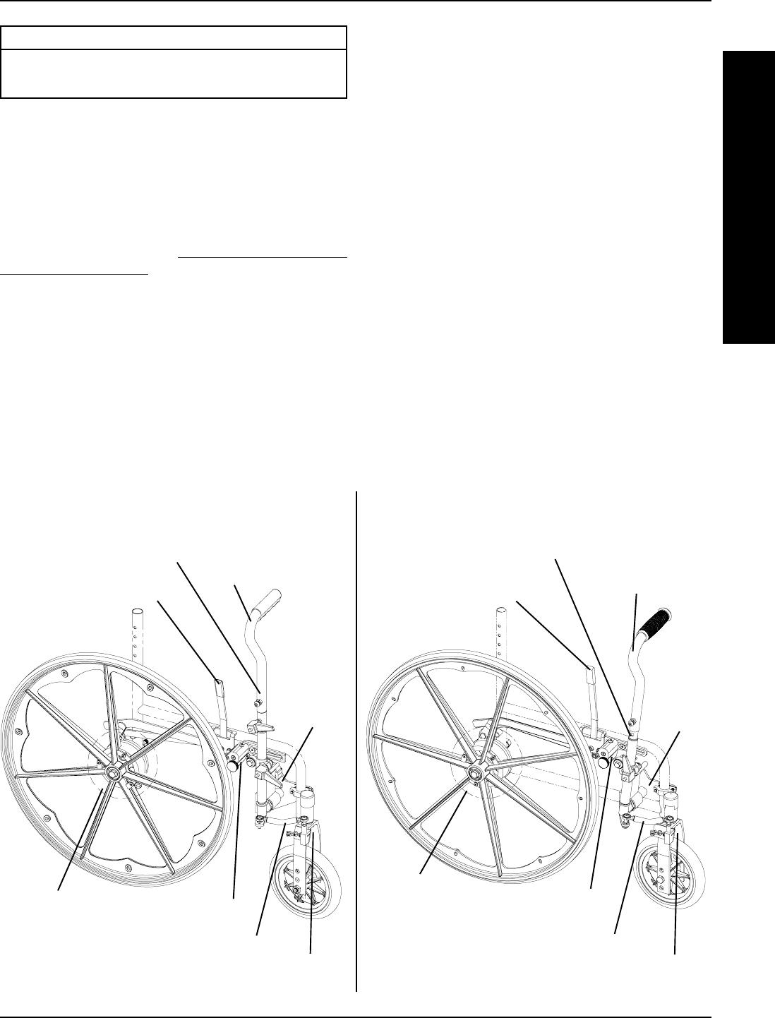
The Cyclical Lever Device (CLD) consists of several as-
semblies shown in FIGURE 1 and described on this page.
For proper installation follow
INSTALLING CLD ON EX-
ISTING WHEELCHAIR in PROCEDURES 1-6 and per-
form PROCEDURE 7.
The following five (5) items are included in each kit. Each
numbered line represents a complete assembly;
Wheelchairs Built BEFORE 09/05/00 -
1. Hub Attachment, Transmission and Wheel Lock
2. Drive Arm Assembly, Support Bracket, and Steering
Link
3. Drive Arm
4. Fork Assembly
5. Front Rigging Release Handle
A
S
S
E
M
B
L
Y
PROCEDURE 1
ASSEMBLY
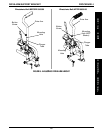
FIGURE 1 - ASSEMBLIES
This Procedure includes the following:
Assemblies
Tools Needed
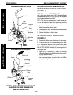
Wheelchairs Built AFTER 09/05/00
1. Transmission and Wheel Lock
2. Drive Arm Assembly, Support Bracket and Steering
Link
3. Upper Drive Arm
4. Fork Assembly
5. Rear Wheel Mounting Hardware
TOOLS NEEDED
NOTE: Have the following tools available.
Torque Wrench
7/16-inch Socket or Box Wrench
7/16-inch Open End Wrench
1/2-inch Socket or Box Wrench
11/16-inch Socket or Box Wrench
3/4-inch Socket or Box Wrench
5/32 Hex Key
3/16 Hex Key
No. 1 Phillips Screw Driver
*M13 Socket or Box Wrench - Wheelchairs Built
BEFORE 09/05/00 ONLY
6MM Hex Key - Wheelchairs Built BEFORE 09/05/00
ONLY
*And adjustable wrench can be used in place of the M13
wrench.
Wheelchairs Built BEFORE 09/05/00 Wheelchairs Built AFTER 09/05/00
Hub
Attachment
(Rear Wheel
Mounting
Hardware)
Steering Link
Wheel Lock
Fork
Assembly
Drive Arm Assembly Upper
Drive
Arm
Transmission
Support
Bracket
NOTE: Right side final assembly shown.
NOTE: Right side final assembly shown.
Transmission
Drive
Arm
Support
Bracket
Fork
Assembly
Steering Link
Wheel Lock
Hub
Attachment
Drive Arm Assembly