


17
W
H
E
E
L
L
O
C
K
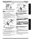
WHEEL LOCK PROCEDURE 5
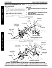
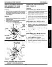
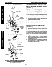
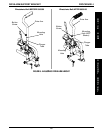
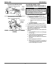
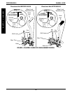
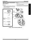
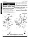
FIGURE 2 - ADJUSTING WHEEL LOCK ASSEMBLY
POSITION
Wheelchairs Built BEFORE 09/05/00
Flat Screws
Wheel Lock Adjustment Rod
Wheel
Lock
Support
Bracket
Wheelchairs Built AFTER 09/05/00
Flat Screws
Wheel Lock Adjustment Rod
Transmission
Support
Bracket
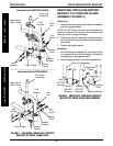
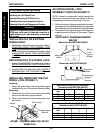
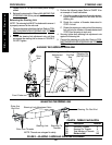
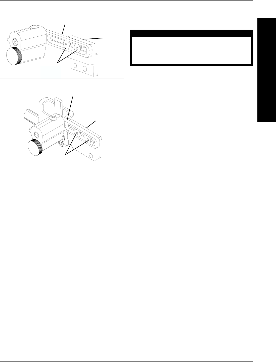
ADJUSTING WHEEL LOCK
ENGAGEMENT POSITION (FIGURE 3)
WARNING
The shift lever MUST be in the neutral position before
activating the wheel lock. Failure to do so can
cause accidental release and make it more diffi-
cult to disengage the wheel lock feature.
1. Place the shift lever in the neutral (center) position.
2. Perform one (1) of the following (DETAIL "A"):
A. HORIZONTAL POSITION - Perform the following:
i. Pull the knob on the wheel lock block OUT.
ii. Rotate the wheel lock block to the vertical po-
sition.
iii. Release the knob.
B. VERTICAL POSITION - Proceed to STEP 3.
3. Pull BACK on the drive arm until the wheel lock engages.
4. Ensure that there is a minimum of 1/4-inch engage-
ment between the wheel lock block and the outside
edge of the rear tire (DETAIL "A").
5. If the engagement is less than 1/4-inch, perform the
following:
A. Push FORWARD on the drive arm to disengage
the wheel lock.
B. Loosen, but DO NOT remove the two (2) flat screws
securing the wheel lock adjustment rod.
C. Slide the wheel lock adjustment rod towards the
rear wheel.
D. Tighten the flat screws until secure.
E. Repeat STEPS 3-5 until there is a minimum of
1/4-inch engagement between the wheel lock block
and the outside edge of the rear tire.