


14
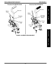
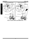
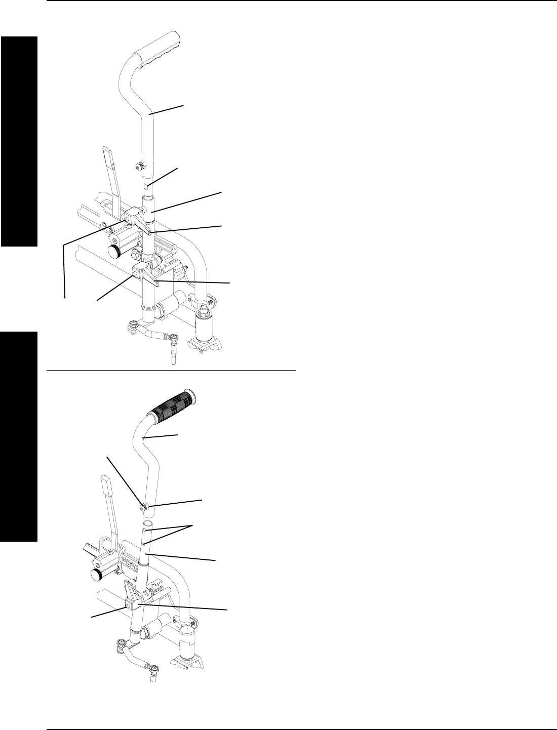
Wheelchairs Built AFTER 09/05/00
Wheelchairs Built BEFORE 09/05/00
Drive Arm
Flat
Surface
Drive Arm
Release
Lever
Plunger
Extension
Tube
Button
Button
Screw
Drive Arm
Mounting Holes
Mounting
Hole (NOT
Shown)
Plunger
Tube
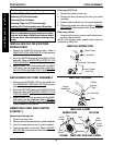
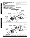
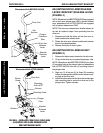
FIGURE 4 - INSTALLING/REMOVING DRIVE ARM
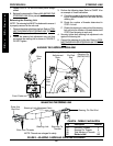
- ADJUSTING DRIVE ARM RELEASE LEVER/
BRACKET RELEASE LEVER
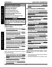
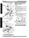
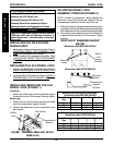
ADJUSTING DRIVE ARM RELEASE
LEVER/BRACKET RELEASE LEVER
(FIGURE 4)
NOTE: Wheelchair built BEFORE 09/05/00 are equipped
with a drive arm release lever AND a bracket release
elver, wheelchairs built AFTER 09/05/00 are equipped
with a bracket release lever ONLY.
NOTE: The drive arm release lever/ bracket release le-
ver can be rotated to keep it from protruding from the
drive arm.
1. Depress and hold the button on the drive arm re-
lease lever/bracket release lever.
2. Rotate the drive arm release lever/bracket release
lever to the desired position.
3. Release the button to lock in place.
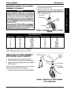
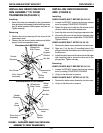
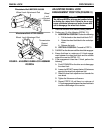
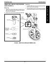
ADJUSTING DRIVE ARM HEIGHT
(FIGURE 5)
1. Remove the button screw located on the drive arm.
2. Lift up on the drive arm to expose the plunger tube.
NOTE: Wheelchairs built BEFORE 09/05/00 have three
(3) mounting holes in the plunger tube and wheelchairs
built AFTER 09/05/00 have two (2) mounting holes in
the plunger tube.
3. Align one (1) of the two (2) (or three (3)) mounting
holes in the plunger tube with the button screw mount-
ing hole on the drive arm.
4. Install the button screw into the drive arm and plunger
tube mounting hole to secure the drive arm to the
plunger tube. Tighten securely.
Bracket
Release
Lever
Button
Bracket
Release
Lever
D
R
I
V
E
A
R
M
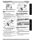
DRIVE ARM/SUPPORT BRACKETPROCEDURE 4
S
U
P
P
O
R
T
B
R
A
C
K
E
T