


accurately. If connected in wrong way, the output port of the indicator or the input port of
computer communication will be damaged, and sometimes the damage will happen to the
indicator, computer and peripherals.
▲! Special computer operation skills and programming ability is required for computer
communication operation, which shall be performed and directed by qualified service
personnel only. Non-professionals are supposed to be out of connection operation.
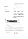
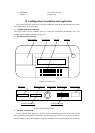
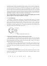
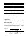
1. The communication port adopts the 15-pin plug (jointly used with the scoreboard). Pins
layout and definition is shown in Figure 6: 6,7,8 (RS232) , and, 1,2,3,4(RS422/485)
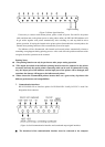
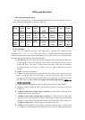
2. All datum are ASCII and each set is composed of 10 bits:1 start bit, 2-9 data bit, 10 stop
bit.
Communicating methods are classified as follows:
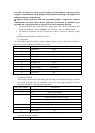
1). In Sequence:
The data transmitted is the present weight displayed (gross or net), each frame of datum is
composed of 14 sets of datum. Hereunder is the format:
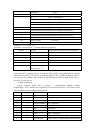
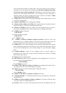
Byte Serial Number Descriptions
1 02H(XON) begin
2 + or - symbol bit
3 Weighing data high bit
… Weighing data …
… Weighing data …
10 Weighing data low bit
11 Decimal from right to left (0~4)
12 XOR verifying high 4 bits
13 XOR verifying low 4 bits
14 03H(X0FF) end
XOR=2 ⊕ 3 ⊕ 4 …8 ⊕ 9
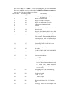
2). Instruction method
The indicator transmits the corresponding data according to the instruction of upper computer.
One frame of datum will be transmitted every time when upper computer send one
instruction. Hereunder is the instruction transmitted:
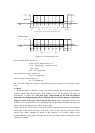
Byte Serial Number Descriptions
1 02H(XON) begin
2 A~Z address serial number
A~B order A: Handshaking
Order B: Read the displayed weight
3
4 XOR verifying high 4 bits
5 XOR verifying low 4 bits
6 03H (X0FF) end
XOR= 2 ⊕ 3
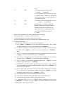
The output content of indicator:
Byte Serial Number Descriptions