


characters, counts from the transmitting head
12 1 End sign 03H
44 bytes in total
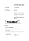
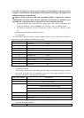
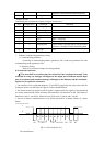
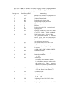
Transmitting the accumulated weight by using the format below:
Sect Length (byte) Definition Descrition
1 1 Beginning sign 02H
2 1 Transmitting head A~Z, representing indicator address
3 4 Sign “SUM=”
4 11 Weight ASCII character string
5 3 Unit space + t/kg/g/mg
6 1 Enter key 0DH
7 2 Verifying sum 1 byte (in hex) verifying sum in 2 bytes ASCII
characters, counting from the transmitting head
8 1 End sign 03H
24 bytes in total
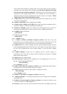
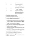
3. Indicator communicating parameter setting:
1). Communicating parameter
Consisting of communicating address (parameter P21), baud rate (parameter P19) and
communicating mode (parameter P20).
2). Parameter Setting
Refer to Keys Function chapter for setting methods
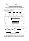
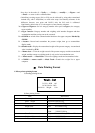
8. Scoreboard Connection
▲! The down-lead of scoreboard must be connected to the scoreboard accurately. If be
connected in wrong way, damages will happen to the output port of indicator and the input
port of scoreboard, and sometimes damage will happen to the indicator and the scoreboard.
Special wire is required in connection.
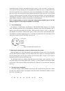
1. The interface of the scoreboard adopts the 15-pin RS232 plug (using the same socket with the
COM port). Refer to 9 and 10 pin in Figure 6 for down-lead definition:
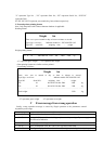
2. The 20mA current loop signals or RS232 signals is supposed to be the signals of scoreboard and
are serially transmitted by means of binary coded character with baud rate as 600. Each frame of
datum has 11 bits: 1 start bit (0), 8 data bits (low bit in front), 1 sign bit and 1 stop bit.
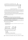
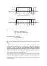
3. One set of datum is transmitted once every 200ms and each set of datum consists of 3 frame
datum.
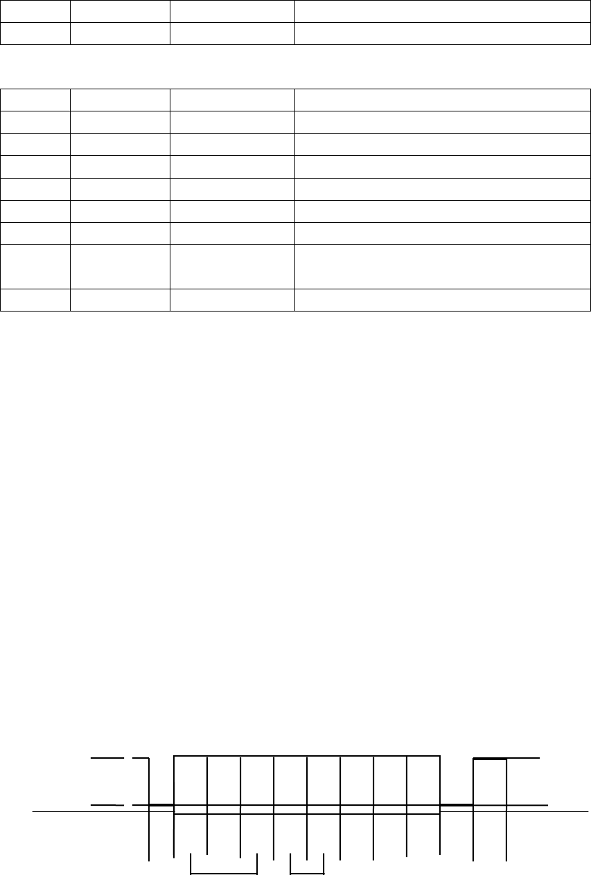
The first frame:
1
0
bit 0 1 2 3 4 5 6 7 8 9 10
d0 d1 d2 d3 d4 d5 d6 d7
start sign stop
bit X Y G18 G16 G17 bit bit
(图 6.1 ) The first frame view
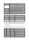
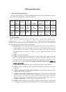
The second frame: