Endpoint Block Plus v1.8 for PCI Express www.xilinx.com 13
UG343 June 27, 2008
R
Chapter 3
Quickstart Example Design
This chapter provides an overview of the Endpoint Block Plus for PCI Express example
design (both single and dual core) and instructions for generating the core. It also includes
information about simulating and implementing the example design using the provided
demonstration test bench.
Overview
The example simulation design consists of two discrete parts:
• The Downstream Port Model, a test bench that generates, consumes, and checks PCI
Express bus traffic.
• The Programmed Input Output (PIO) example design, a completer application for PCI
Express. The PIO example design responds to Read and Write requests to its memory
space and can be synthesized for testing in hardware.
Simulation Design Overview
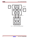
For the simulation design, transactions are sent from the Downstream Port Model to the
Block Plus core and processed by the PIO example design. Figure 3-1 illustrates the
simulation design provided with the Block Plus core. For more information about the
Downstream Port Model, see Appendix B, “Downstream Port Model Test Bench,” in the
LogiCORE IP Endpoint Block Plus for PCI Express User Guide.


