


052124 Rev. D
19
ENGLISH
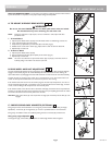
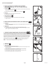
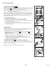
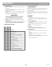
P. REAR WHEEL SPACING
Rear wheel spacing is measured as the gap between the top of the rear wheels and the backcanes, and is
shown as dimension X . Available factory range: .75" to 1.75". The widest setting is typically required
to provide adequate tire clearance when using the height adjustable armrest option.
NOTE– When setting the rear wheel spacing only make adjustments to one side of the chair at a time.
Loosening both sides will undo the toe setting.
To adjust the rear wheel spacing, the camber inserts (E) telescope in and out of the axle bracket (F). On
the left side of the chair, loosen screws (G). Slide the camber insert in or out to establish the required
wheel spacing. Tighten screw to 144 in-lbs. (16.3 Nm). Repeat on the right side of the chair, matching
the wheel spacing set on the left side. Ensure toe in/out maintains proper setting (see Section O-4:
Setting Toe-in Toe-out to Zero).
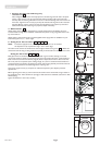
Rear Wheel Axle Adjustment
Tight axle sleeves should be maintained for proper performance of the wheelchair.
a. To adjust the axle you will need a 3/4" wrench to turn the outside axle nuts.
b. You will also need a 1/2" wrench to lodge the ball bearings, on the opposite end of the axle, and
prevent the axle from turning.
c. Turn the outside axle nut counterclockwise to tighten.
d. There should only be zero to ten thousandths of an inch (.010") of play (see Section B: Rear
Wheel Axle Nut Adjustment).
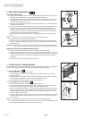
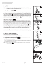
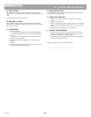
Q. WHEEL LOCKS
Quickie GTX Swing-Away and Quickie GTX Fixed Front wheelchairs are shipped with one of five types of
wheel locks. Wheel locks are installed at the factory unless you have requested otherwise.
Use a torque setting of 100 in.-lbs. when setting up wheel locks.
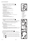
1. High-Mount Push-to-Lock or Pull-to-Lock , One-Hand/Unilateral
Wheel Locks Adjustment
a. Using a 5mm Allen wrench, turn one of the screws in the clamp counterclockwise one-quarter
turn.
b. Repeat the same process with the second of the two screws.
c. Alternately loosen the screws (two turns each) until both screws are removed.
d. Slide clamp toward the rear wheel until the wheel lock is embedded into the tire to prevent
wheel movement, when in the locked position.
e. Tighten screws to 144 in-lbs. (16.3 Nm).
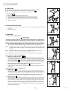
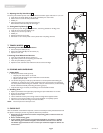
2. Ergo Scissor Wheel Locks or Short Throw Scissor Wheel Locks
Loosen the screws (B) on the top of each clamp using a 5mm Allen wrench. Slide assembly toward rear
wheel until clamp embeds into tire to prevent wheel movement when in locked position. Adjust angle posi-
tion. Tighten screws to 144 in-lbs. (16.3 Nm).
NOTE– Clamp and wheel lock may need to be rotated to clear frame tubing.
37
3635
33
3433
34
33
G
E
X
equal
35
36
B
37