


052124 Rev. D
17
ENGLISH
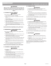
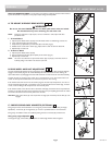
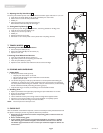
M. SEAT SLING
The seat sling can be adjusted through the use of hook and loop material beneath the seat.
Seat sling also includes a folding strap on the seat to assist in folding the chair.
NOTE– The seat sling folding strap is not intended as a carrying strap.
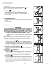
1. Adjustment
a. Remove seat rail end caps at the front of the chair (A).
b. Slide the seat sling and plastic retaining rods from the channels in the seat rails.
c. Readjust hook and loop material to obtain the desired tension in the seat sling.
d. Reinsert the seat sling and plastic retaining rods into the channels in the seat rails.
e. Replace the end caps.
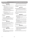
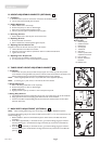
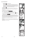
N. CUSHION INSTALLATION
a. Place cushion on seat sling with hook material side down. The beveled edge of the cushion should
be in front.
b. Press firmly into place.
O. REAR AXLE
1. Center of Gravity Adjustment
WARNING
The more you move your rear wheels forward, the more likely your chair will tip
over backwards. Always make adjustments in small increments, and check the sta-
bility of your chair with a spotter to prevent a tip-over. We recommend that you
use anti-tip tubes until you adapt to the change and are sure you are not at risk to
tip over. Refer to additional Warnings in Section VI “Falls and Tip Over”.
NOTE– Changes to the center of gravity may affect the rear seat height, toe-in/toe-out of the rear wheels and
the squareness of the casters. If you change your center of gravity position, re-adjust all of these settings
if necessary.
NOTE– Adjusting your chair’s center of gravity will require re-adjusting the location of the wheel locks
(if provided). See Section “”Q” for instructions on adjusting the wheel locks.
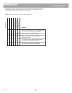
The GTX Swing Away and GTX Fixed Front has two methods of adjusting Center of Gravity (CG).
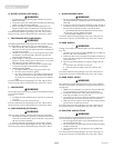
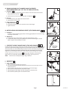
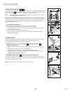
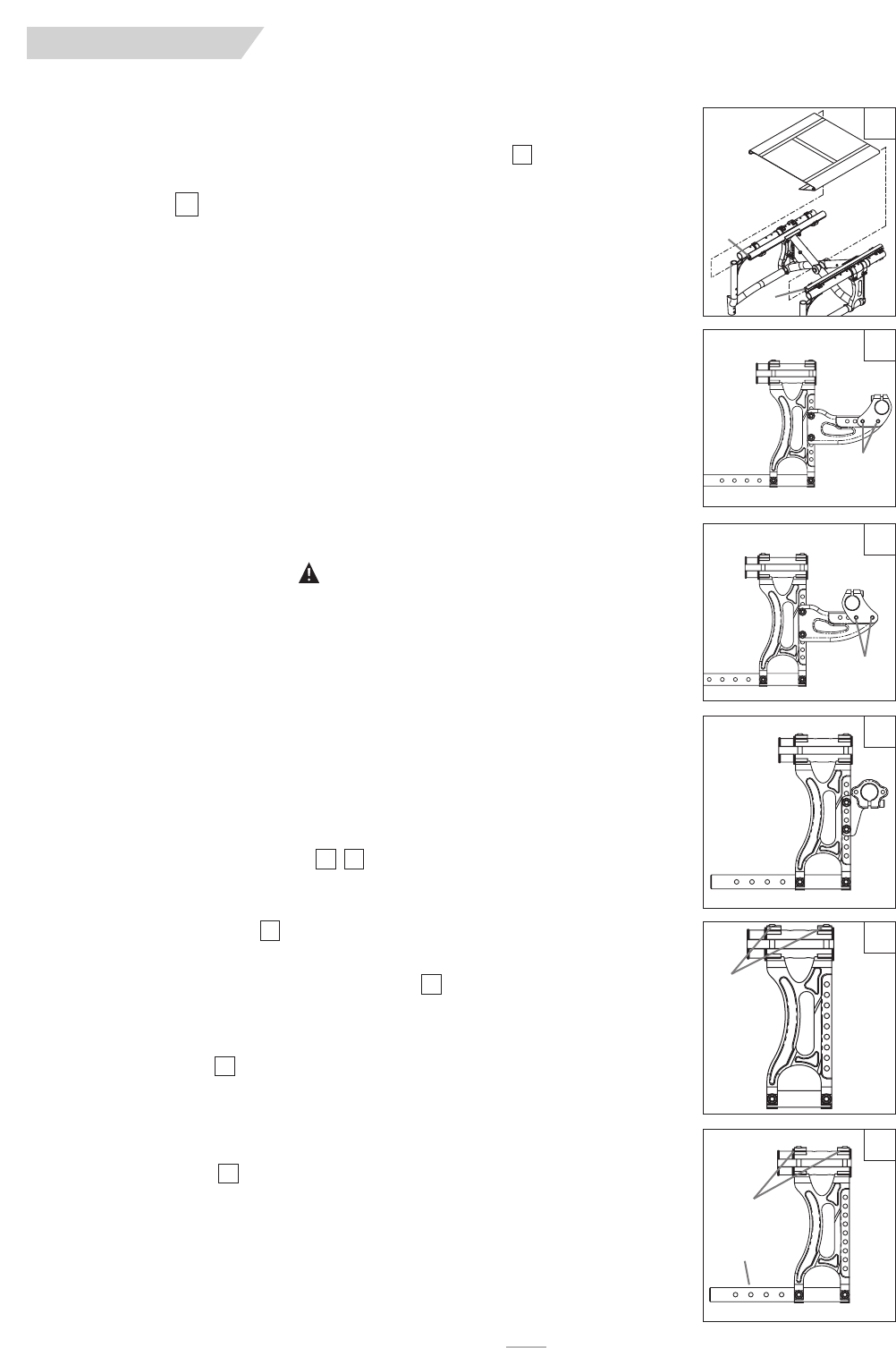
2. Primary Center of Gravity Adjustment
a. GTX Swing Away & Fixed Front
Place the entire wheelchair on a flat horizontal table or ground surface. Remove both rear wheels
from wheelchair. Remove the four screws, washers and nuts (A) (2 per side). Thus allowing the axle
sleeve clamp to be repositioned in desired location. Axle sleeve clamp can also be reversed to achieve
greater range of adjustment . Note, if reversing the axle sleeve clamp switch the left side clamp
with the right side to eliminate the need to remove and flip axle sleeves. Reinsert four screws (A) (2
per side), washers and nuts to secure sleeve clamp. Tighten screws to 144in-lbs. (16.3Nm)
b. GTX Swing Away and Fixed Front using Short Axle
There is no primary Center of Gravity adjustment with the short axle. See Section 3 for second-
ary adjustment.
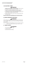
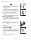
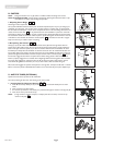
3. Secondary Center of Gravity Adjustment
a. GTX Fixed Front
Place the entire wheelchair on a flat horizontal table or ground surface. Unlatch footplate from
locked position (Note, not necessary for Auto Folding footrest option). Remove both rear wheels
from wheelchair. Remove four screw screws (A) atop the axle plate (2 per side) and reposition into
desired location by sliding along frame. Securely tighten all four screws (A) (2 per side). Tighten
screws to 88in-lbs. (10Nm). Ensure that axle plates are positioned symmetrically on frame.
b. GTX Swing Away
Place the entire wheelchair on a flat horizontal table or ground surface. Remove both rear wheels
from wheelchair. Remove four screw screws (A) atop the axle plate (2 per side) and two lower
frame screws (B) (1 per side). Reposition into desired location by sliding along top frame and tele-
scoping in our out of the lower frame. On lower frame adjust plastic sleeve to cover telescoping
tube. Securely tighten all four screws (A) (2 per side) atop the axle plate and two lower frame
screws (B) (1 per side). Tighten screws to 88in-lbs. (10Nm). Ensure that the axle plates are posi-
tioned symmetrically on frame.
26
25
24
23
2322
21
21
21
A
A
22
A
23
A
A
25
26
A
B
24