


052124 Rev. D
16
ENGLISH
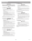
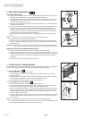
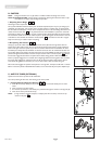
K. BACK ANGLE ADJUSTMENT
Adjusting the Back Angle
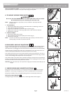
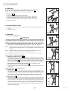
1. Using a 4mm Allen Key and 10mm wrench on opposite side completely remove the pivot screw
(A) that attaches the back tube (C) to angle adjustable backrest bracket (B).
2. For folding back, loosen but don’t remove cam stop (D) using a 4mm Allen Key and wrench. For
non folding back, loosen but don’t remove 6mm socket screw (E) and loosen but don’t remove
both lower 6mm button head screws (F)
3. Determine new angle by aligning the upper hole in the backrest tube (C) with the different holes
in the backrest bracket (B).
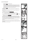
4. Once proper hole is determined, while aligning hole in one end of the pivot washer with proper
hole, insert pivot screw (A) through proper hole in outside wall of backrest bracket (B) and
through the hole in pivot washer. Continue to feed screw through both walls of backrest tube
(C). Wrap pivot washer around front of backrest tube and align remaining hole in pivot washer
with proper hole on the inner wall of backrest bracket (B).
5. Once in place using a 4mm Allen Key and 10mm wrench tighten the pivot screw (A) back into
place.
NOTE– For folding back, do not over tighten. Backrest must be allowed to fold easily.
6. Repeat procedure to the other side of the wheelchair.
7. Adjust and tighten cam stops for both sides of the wheelchair (D), see steps below for folding
back. For non folding back tighten 6mm socket screw (E) and tighten 6mm button head screws
(F) back into place.
CAUTION – When changing the back angle of the wheelchair both the left and right angle adjustable back
bracket must be in the same hole position (see steps 3 &4) before the wheelchair is to be used.
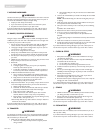
Adjusting the Cam Stop (Folding Back Option Only)
1. Once the proper back angle is set tighten the cam stop screw (D) back into place
2. Using a 10mm open-ended wrench on the inner hex drive of the cam stop, rotate the cam stop
to eliminate excessive play in the back tube. Verify that backrest latches into place. If backrest will
not latch, adjust cam away from tube until back tube latches freely, while still minimizing play in
the backrest.
3. Check that the cam stop screw is tightened into place. (D)
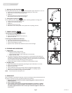
L. FITTING THE JAY
®
PRECISION BACK
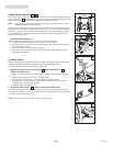
The Jay Precision Back is a tension adjustable back that includes lateral support hardware. It is designed to
follow the contour of the back of the end user and provide beneficial lateral trunk control.
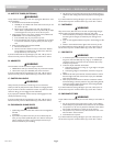
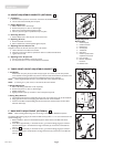
1. Contour Adjustment
a. To modify the contour of the Jay Precision Back:
Pull the tensioning straps (A) inward to increase the tension and lift the tab of the tension lock
buckle to release it.
b. To adjust the Jay Precision Back to conform with the user’s anatomy, release tension on all straps
then adjust them proceeding from the base of the back upholstery moving up.
c. These adjustments should be done with the user sitting in the chair.
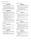
2. Lateral Supports Location Setting
a. Remove the lateral covers (B). Leave the lateral support foam pads on.
b. To move the lateral supports up or down loosen the screws (C) and slide them vertically until
desired location is obtained, tighten the screws to secure the lateral supports.
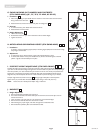
c. Should more adjustment be required, two more openings are available on the back cane envelopes
to allow for height adjustment of the hardware itself. To relocate the hardware loosen the screws
(D) of the clamp until it can be taken off the cane. Move the clamp and hardware up or down as
needed and tighten the screws firmly.
d. The lateral supports have 2 inches of adjustment range towards the inside from the external plane
of the back canes. To adjust, loosen the screws of the clamp (D), set the adjustment and tighten
them back down.
NOTE– If adjustment pushes too far inward it will prevent the chair from folding completely.
e. If adjusted too low, the lateral supports may interfere with the cross brace when folding the chair.
f. These adjustments may be done with the user sitting in the chair.
20
19
1817
A
19
B
C
D
20
18
17
A
B
D
E
F
F
C