


052124 Rev. D
18
ENGLISH
32
D
C
parallel
31
D
30
C
A
Toe in
Toe out
29
H
28
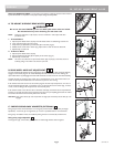
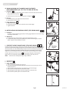
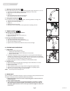
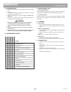
c. Reposition Seat Sling Tube- GTX Swing Away
and Fixed Front
After making Secondary Center of Gravity adjustment the seat sling tube will need to be reposi-
tioned. Loosen the four nuts (A) (2 per side) that hold the seat sling tube to the cross brace
assembly. Slide the seat sling tube either fore or aft to make the seat sling tube even with the rear
frame tube. Tighten the four nuts (A) (2 per side) that hold the seat sling tube to the cross brace
assembly, 88in-lbs. (10Nm). Ensure front seat sling tube position screw (B) lines up with slot in
saddle. Check both side of seat sling for proper fit, readjust if necessary.
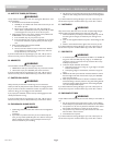
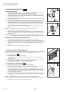
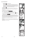
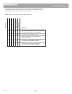
4. Wheel Camber
Wheel camber, shown as angular relationship (H), provides greater side-to-side stability due to the
increased width and angle of the wheelbase. It also allows for quicker turning and greater access to the
top of the handrims.
Wheel camber is determined by pairs of interchangeable camber plugs which are available from your
authorized supplier in 0º, 2°, and 4º angles.
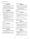
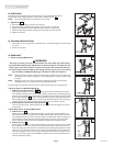
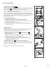
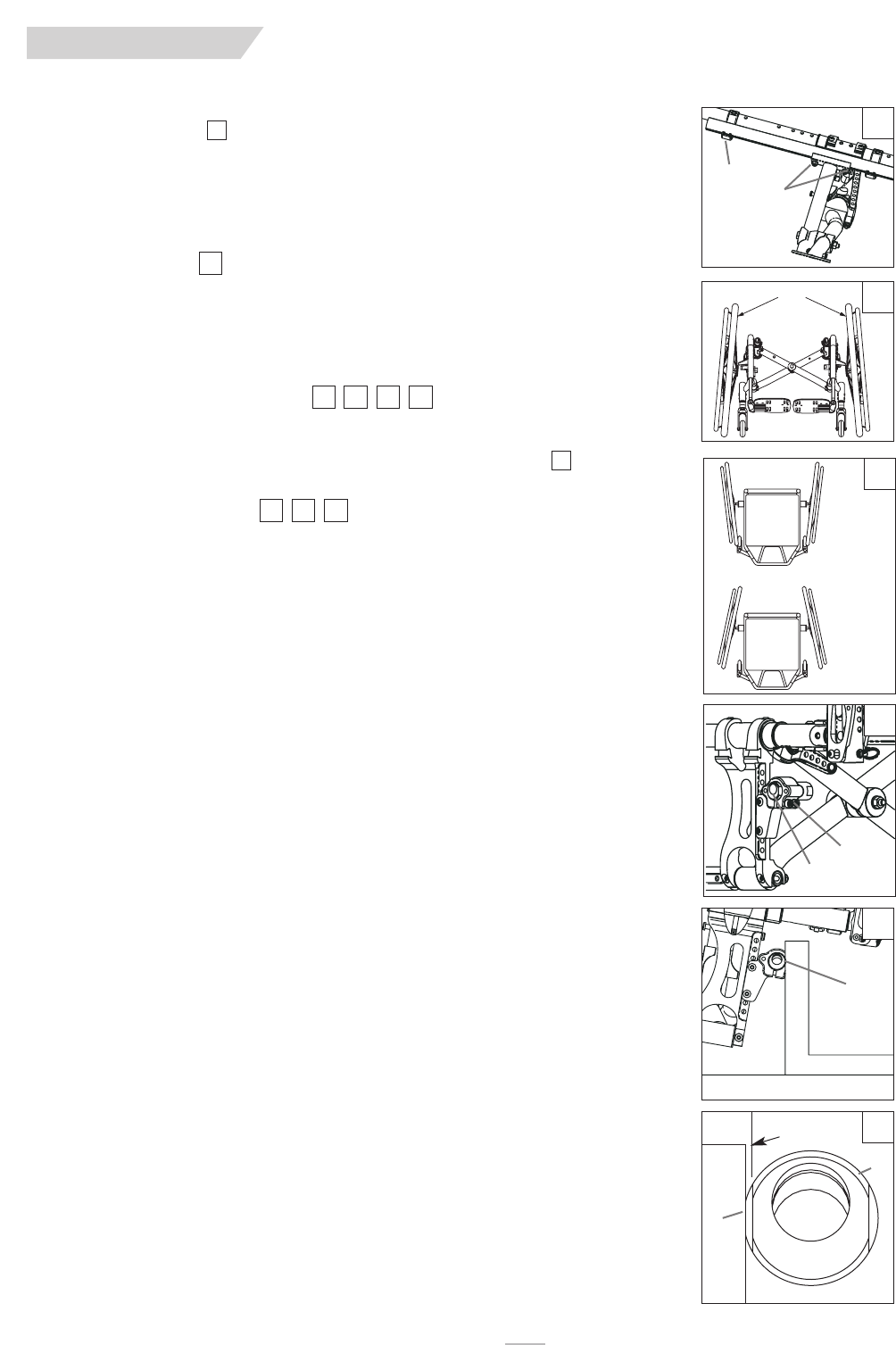
5. Setting Toe-in Toe-out to Zero
NOTE– A wheelchair equipped with 0° camber plugs cannot have a toe-in toe-out condition.
This adjustment is only required when using 2° and 4° camber plugs.
Toe refers to how well the rear wheels of the chair are aligned relative to the ground . It affects how
well the chair will roll. Drag or rolling resistance is optimally minimized when the wheel toe is set to zero.
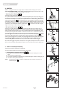
Setting the Toe to Zero
Safely place the entire wheelchair on a flat horizontal table or ground surface. Starting on one side,
remove rear wheel, and loosen the 2 screws (A) that secure the camber tube clamp. Locate the flat sur-
faces on the front and rear of the camber plugs (D). Place an object that is known to have an accurate
90° corner (such as a carpenters square, drafting triangle, etc.) down on the flat horizontal surface and
up against the flat of the camber plug. Rotate the camber tube and plug assembly until the flat surface of
the camber plug is parallel to the vertical edge of the measuring tool.
Once square, tighten screws (A), and place rear wheel securely back in place. Repeat process for
opposite side.
Before tightening the screws (A), make certain that the camber tube is centered left-to-right relative to
the wheelchair frame. There should be an equal gap on both sides of the wheelchair (see section P: Rear
Wheel Spacing).
Tighten the fasteners to 144 in-lbs. (16.3 Nm).
323130
29
32313029
28
27
27
B
A