


052124 Rev. D
13
ENGLISH
IX. SET-UP, ADJUSTMENT & USE
NOTE ON TORQUE SETTINGS: A torque setting is the optimum tightening which should be made on
a particular fastener. It is important to use proper torque settings where specified.
A. TO MOUNT & REMOVE REAR WHEELS
WARNING
Do not use this chair UNLESS you are sure both quick-release axles are locked.
An unlocked axle may come off during use and cause a fall.
NOTE– Setting the wheelchair on a flat surface, such as a workbench or table, helps make these
procedures easier.
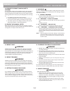
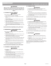
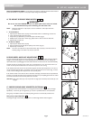
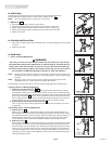
1. To Install Wheel
a. Depress quick-release button (A) fully. This will release tension on ball bearings at other end.
b. Insert axle (B) through hub of rear wheel.
c. Keep button (A) depressed as you slide axle (B) into camber plug (C).
d. Release button to lock axle in camber plug. Adjust axle if it does not lock. See Section B.
e. Repeat steps on other side.
2. To Remove Wheel
a. Depress quick-release button (A) fully.
b. Remove wheel by sliding axle (B) completely out of camber plug (C).
c. Repeat steps on other side.
NOTE– The axle is not locked until the quick-release button pops out fully (A). Check that the axle is
locked by pulling on the wheel in the direction of the axle.
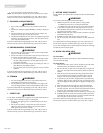
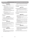
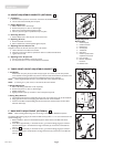
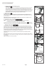
B. REAR WHEEL AXLE NUT ADJUSTMENT
The rear wheel axle (B) attaches the rear wheel (D) to the camber plug (C). When the detent balls (E)
engage into the camber plug the rear wheel effectively becomes locked onto the chair. Pushing the
quick-release button (A) disengages the detent balls and allows removal of the axle and wheel assembly.
To adjust the axle you will need a 3/4" wrench to turn the adjustment nut (F). You will also need a 1/2"
wrench to securely hold the ball detent end of the axle to prevent it from turning.
If the wheel and axle will not lock into the camber plug then the axle requires adjustment. Turn the nut
counter-clockwise approximately 1/4 revolution and try to lock the axle into the camber plug. If it does-
n't lock, continue making small nut adjustments until it securely locks.
If the wheel is locked on the chair but there is excessive wheel play (the wheel hub can be pushed back
and forth on the axle) then adjust the nut clockwise until there is no perceptible gap between the wheel
and camber tube and the axle is securely locked onto the chair.
CAUTION– Quick-release button (A) must be flush with the edge of the wheel hub for detent balls (E) to be
engaged.
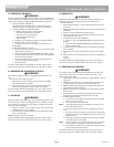
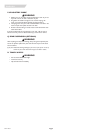
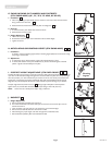
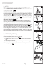
C. PADDED SWING-AWAY ARMRESTS (OPTIONAL)
Swing-away armrests can be detached or can swing away to allow lateral transfers. They are height
adjustable (1" increments) by moving bolts (A) up or down in predrilled holes on armrest bracket.
Swing-away, removable armrests are installed by sliding armrest into receiver (B) on back frame.
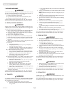
Swing-away, angle adjustable
To change the angle, remove bolts (C), reposition to needed angle. Reinsert bolt and tighten.
6
5
43
21
A
B
C
1
2
3
4
B
E
F
A
A
C
D
E
5
A
C
B
6