


052124 Rev. D
14
ENGLISH
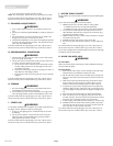
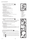
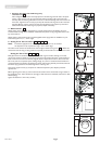
D. HEIGHT-ADJUSTABLE ARMRESTS (OPTIONAL)
1. Installation
a. Slide the outer armpost into the receiver mounted to the wheelchair frame.
b. The armrest will automatically lock into place.
2. Height Adjustment
a. Rotate release lever to second stop.
b. Slide armrest pad up or down to desired height.
c. Return lever to locked position against armpost.
d. Push arm pad until upper armpost locks firmly into place.
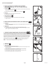
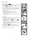
3. Removing Armrest
a. Rotate release lever to first stop and remove the armrest.
4. Replacing Armrest
a. Slide armrest back into receiver.
b. Return release lever to locked position against armpost.
5. Adjusting Armrest Receiver Fit
To tighten or loosen the fit of the outer armpost in the receiver:
a. Loosen the bolts on the sides of the receiver.
b. With the armrest in the receiver, squeeze the receiver to achieve the desired fit.
c. Tighten the four bolts.
6. Adjusting Inner Armpost Fit
a. Two set screws are installed in the outer armpost.
b. Turn the set screws in or out until the desired fit is achieved.
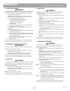
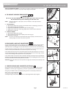
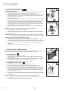
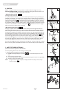
E. THREE-POINT HEIGHT ADJUSTABLE ARMREST
1. Installation
Attach lower rear pivot post (A) to back cane (B). Upper rear receiver (C) will clamp to back
cane. Attached mounting hardware (D) to front of frame so that the hardware is horizontal to the
locking mechanism of the armrest. Ensure all bolted hardware is firmly attached.
NOTE– 3 Point Height Adjustable Armrest is only available with tension adjustable upholstery.
NOTE– If converting to a 3 point armrest, a new backrest tube will be needed.
2. Height Adjustment
a. Push in the locking release lever under armpad (E).
b. Slide armrest pad up or down to desired height.
c. Release locking lever.
d. Slightly push the armpad up and down to ensure armpost firmly locks.
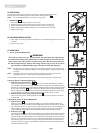
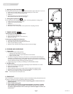
3. Swing Away Armrest
a. Pull release handle upward (F) while lifting the armrest up and towards the rear of the wheelchair.
b. Safely guide the armrest to its stopping point behind the rear of the wheelchair.
c. To lock armrest back into place safely guide the armrest forward and downward until front locks
back into receiver (D).
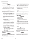
F. BACK DEPTH ADJUSTMENT (OPTIONAL)
NOTE– Before installing offset seating review the warning in Section VIII-O: Modified Seat Systems.
The optional offset seating plug (G) can locate the back canes (H) either 1" or 2" more rearward than the
standard seating plug.
1. Before installation, determine which backrest system will be used and the offset that will be
established.
2. If the offset is approximately 1” then fasten screws ( J) so that the seating plug (G) is inserted in
the frame allowing for 1 inch between the edge of the frame (K) and the front of the backrest
spline (L) .
3. If the offset is approximately 2” then fasten screws ( J) so that the seating plug (G) is inserted in
the frame allowing for 2 inches between the edge of the frame (K) and the front of the backrest
spline (L) .
9
9
9
8
7
Height-Adjustable
Armrest Key
1. Outer armpost
2. Standard receiver
3. Release lever
4. Armrest pad
5. Transfer bar
6. Side panel
7. Outer armpost tension
adjustment set screws
8. Inner armpost
9. Receiver adjustment
hardware
10. Release Lever
1
10
6
7
8
3
5
9
2
7
4
8
9
J
H
L
K
offset
G
D
A
C
B
F
E
M
N
10