


Theory of Operation and System Architecture
Training
11-7
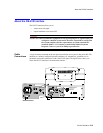
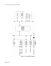
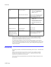
Isolated
Front End
The Isolated Front End section includes all of the circuitry to convert ECG, SpO
2
, and
Temperature measurements to digital format; and to connect this information to the processor.
The Respiration detection is obtained from two of the three electrodes of the ECG
connections.
NBP Front
End
The NBP section contains the pumps, valves, pressure measurement circuitry, and control
circuitry for the non-invasive blood pressure measurement. Pressure data is converted to
digital format and conveyed to the processor section.
Power
System
The power system section contains a power supply capable of operating the monitor and
charging the battery from an AC source of 100 to 240 VAC at 50 to 60 Hz. This section also
contains the circuitry. The battery provides the operating power for this power.
Micro-
processor,
Memory and
Control
The Microprocessor, Memory and Control section contains the system CPU and all digital
support circuitry. The latter includes the RAM, non-volatile memory, and real-time clock.
This section also contains the display logic, keypad (switch) interface logic, RS-232 I/O
control, defibrillator synchronization control, and printer logic.
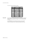
Display The display is a TFT (color), backlit fluorescent LCD unit. The active screen size is 8.3 x 6.2
in (210.8 x 157.5 mm): 10.4 in (264.2 mm) diagonally, and the resolution is 640 x 480 pixels.
Keypad The keypad circuit contains five push-button membrane switches and two green LEDs. The
LEDs are driven by the power supply system and indicate the power source.
Signals from LEDs are returned to the microcomputer for processing and control as required.
The On/Standby button, connected directly to the power supply, toggles the power between
On and Standby modes. When in Standby, the display is blank, and no monitoring is
performed. However, the batteries are charging if an AC source is connected to the rear panel.
The Audio Alarm Control button is connected directly to the processor and to the system
power supply. Pressing this button turns off the battery fuse alarm in the system power
supply. Response of the processor depends upon the action in pressing this button. If
momentarily pressed (less than 2 seconds), alarms are paused temporarily for a preset interval
determined by the menu selection. If pressed twice within 10 seconds, the alarm sounding for
a specific parameter is silenced temporarily for a preset interval determined by the menu
selection. Other alarms, not related to this parameter, can still sound during this period. If
pressed and held for 2 seconds or more, the Audio Off condition is initiated.
The NBP button is connected to the processor. Response of the processor depends upon the
state of NBP operation at the time and the action in pressing this button. If momentarily
pressed, (less than 2 seconds), a single NBP measurement is obtained. If pressed for 2 seconds
or more, the processor initiates a STAT monitoring sequence. Pressing the NBP switch at any
time a pressure measurement is in effect causes the processor to terminate the measurement
and to deflate the cuff.